2022/03/16 04:45 17/18 MS2000, MFC2000 and RM2000 OPERATION
Applied Scientific Instrumentation - https://asiimaging.com/docs/
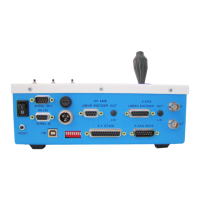
XY Axis Linear Encoder (optional) DB-9M Connector
PIN SIGNAL INFORMATION
9 N.C. Not Connected
Z Axis Linear Encoder (optional) DB-15F Connector
PIN SIGNAL INFORMATION
1 Z Enc Ch A Z Encoder Channel A
2 GND Signal Ground
3 Z Enc Ch B Z Encoder Channel B
4 +5V +5V Power
5-15 N.C. Not Connected
IN BNC (optional)
PIN SIGNAL INFORMATION
Center TTL IN
V
IH
> 3.2V
V
IL
< 1.3V
Outer GND Signal Ground
OUT BNC (optional - TTL)
PIN SIGNAL INFORMATION
Center TTL OUT
V
OH
> 4.4V
V
OL
< 0.1V
IO Max: ±50mA
Outer GND Signal Ground
OUT BNC (optional - Analog)
PIN SIGNAL INFORMATION
Center Analog OUT
0-10 VDC
IO Max: ±3mA
Outer GND Signal Ground
Electrical Characteristics
External Modular Power Supply
AC Input
100-240 VAC, 50/60 Hz, 0.8 A Standard Supply (1.5 A High-Current Supply Option)
DC Output
+24 VDC, 1.25 A Standard Supply (2.5 A High-Current Supply Option)
Fuse
1 Amp, Standard Supply 2 Amp, High-Current Supply