MPS-Series – Installation Guide
U-0664-0174.doc – Issue: 07 complete, approved
Page 17 of 24
3.3.3 Microphone Settings and Build Standard
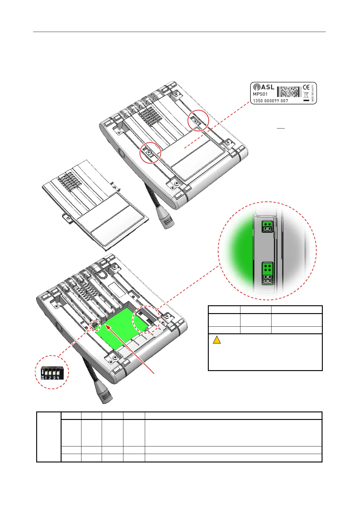
Figure 16 Removing the bottom cover and configuring the microphone
POE
RTR
POE
POE
RTR
RTR
1)
Undo two M4x15 mm screws
(Pan Head Pozidriv).
SW 1 SW 2 SW 3 SW 4 Configuration
DOWN DOWN DOWN DOWN Standard ASL microphone operation (default):
•
Must be used on Emergency Microphones for EN54-16 compliance
•
Firmware upgrade and configuration: via the Ethernet port
•
Configuration via User Interface: read only
UP DOWN DOWN DOWN Bootloader mode: for firmware download via the USB port
DIP
Switch
up=off
down=on
DOWN UP DOWN DOWN Configuration via User Interface: read and write (for commissioning only)
POE Links RTR Links Configuration
Not fitted Fitted
DC power supply via
Router connections
Fitted Not fitted Power over Ethernet
!
!
1) Power over Ethernet does not provide
EN54-16 compliance
2) Disconnect power before changing link
settings
3) POE and RTR links must NOT be fitted
simultaneously
2)
Remove the cover.
3)
Configure the power supply
links.
4)
Fit the micro-SD card
(if used).
5)
Configure the DIP
switches.
The last section of the barcode
indicates the Build Standard (BS).
Example:
1350 000099
007
Æ
BS = 7