V400 – Installation Guide
U-0398-0607.doc – Issue: 03 complete, approved
Page 10 of 24
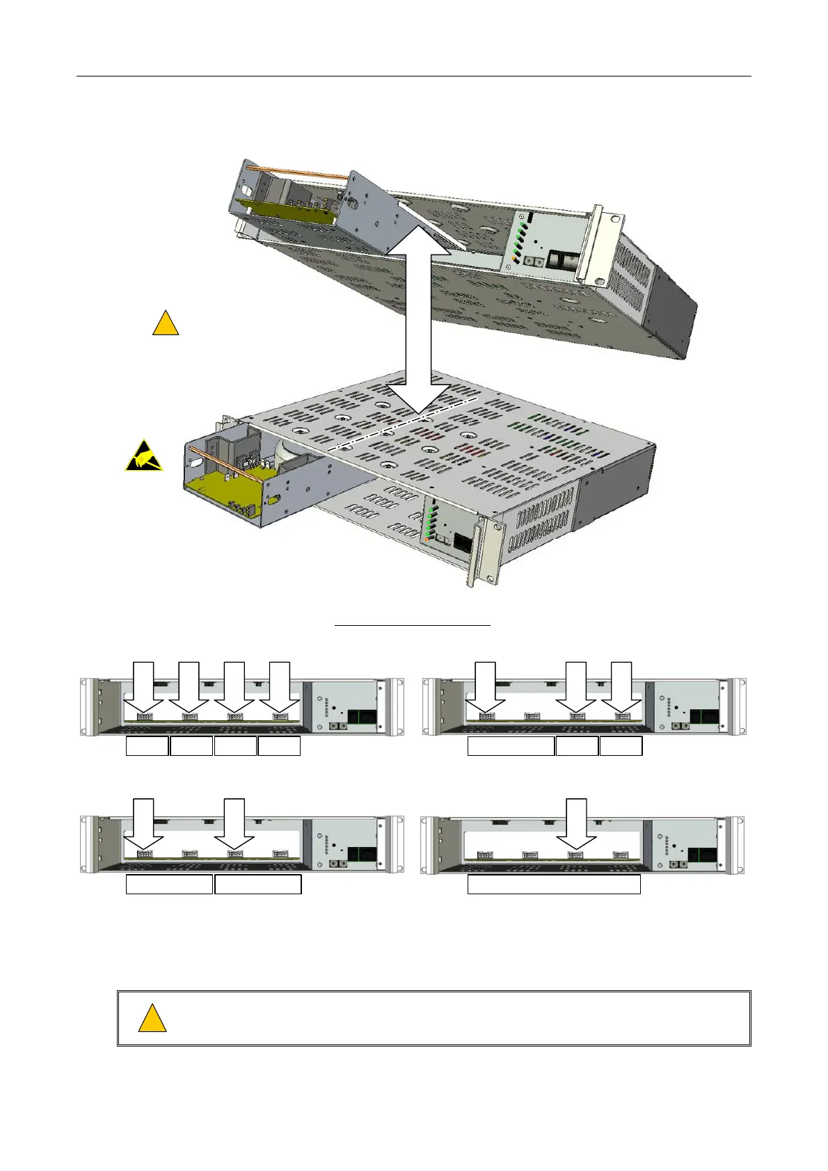
Figure 4 Installing the Amplifier Modules into the V400
4 x M100 CONFIGURATION
1
: 1 x 200 W + 2 x 100 W CONFIGURATION
1
:
MODULE SIDE PANELS MUST
LOCATE IN MAINFRAME SLIDES
!
!
(1 x M200 shown as example.)
M200
M200
MAINFRAME SLIDE
M100
SLOT 1
SLOT 2
SLOT 3
SLOT 4
M100 M100 M100 M200
SLOT 1
SLOT 3
SLOT 4
M100 M100
2 x M200 CONFIGURATION
1
:
M200
SLOT 1
SLOT 3
M200
1 x M400 CONFIGURATION:
M400
SLOT 3
STANDARD CONFIGURATIONS:
1) The mainframe does not need to be fully populated with amplifiers, for example three M100 amplifiers could be fitted, or a sin
le M200 amplifier.
5. If the rack is to be transported, then secure the amplifier modules to each other and to the
mainframe sides using transit screws; see Figure 5.
!
!
Do not transport partially equipped mainframes. Either remove all amplifier modules, or fix all
modules in a fully populated mainframe using transit screws.