V400 – Installation Guide
U-0398-0607.doc – Issue: 03 complete, approved
Page 11 of 24
Figure 5 Fitting the transit screws
FIT THE M3 TRANSIT POZIDRIV SCREWS TO THE
LEFT HAND SIDE OF ALL AMPLIFIER MODULES AS
SHOWN ABOVE.
FIT THE RIGHT HAND M3 TRANSIT POZIDRIV
SCREW ON THE RIGHT-MOST AMPLIFIER
MODULE ONLY AS SHOWN BELOW.
1) The transit screws may be removed when the amplifiers are in situ to facilitate easy removal
of the modules.
2) To remove Amplifier modules, release the transit screws and grip the cross-rod at the front
of the module to slide it from the mainframe.
!
!
The screws attaching the two parts of a M400 amplifier module together should never be
removed.
6. Ensure that the power to the mainframe is disconnected.
!
!
1) Ensure that the mainframe mains and battery switches are turned off; see Figure 6.
2) Ensure that the AC mains supply to the unit is isolated.
3) Ensure that the DC supply to the unit is isolated, if used
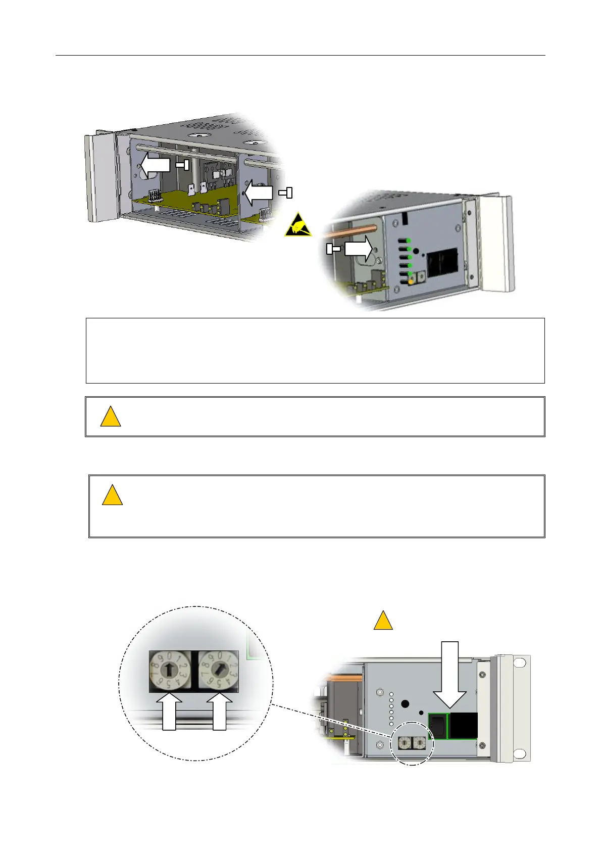
7. Set the mainframe address as specified in the system design documentation; see Figure 6.
Figure 6 Turning the power switches off and setting the mainframe address
EXAMPLE: MAINFRAME ADDRESS 01
O
I
0
1
MAINS AND BATTERY
ISOLATION SWITCHES:
OFF
!
!
 Loading...