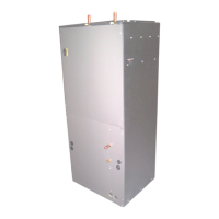
b. Remove access door to reveal pump. Close supply
valve ("A") and return valve ("B"). Open the air bleed
valve to de-pressurize the system and drain water.
c. Remove the metal pump housing by loosening the
four screws on the pump. DO NOT UN-SOLDER PUMP.
d. Replace the new pump housing assembly and
reconnect components to the pump. Before assembling,
make sure that the runner on the o-ring is in place on the
pump housing.
e. Purge the system of the air as described earlier and
re-connect the electrical power.
Common Problems and Solutions
1) Noisy Pump
System may not be totally purged of air. Purge the
system again as described in the start up section above.
2) T&P valve on water heater weeps
This nomally occurs when a backflow preventer has been
installed in the cold water supply line to the water heater. An
expansion tank may be necessary to correct this problem.
Please contact a qualified plumbing professional for assitance.
3) Hot water is circulating through the water coil during
cooling cycle
The check valve may be stuck open and allowing hot water to
circulate through the coil.
4) Little or no heat from water coil
a. Purg the system
b. The inlet connections may be reversed at the fan coil
c. Water heater thermostat is not set at proper temp
d. Water heater thermostat is not caliberated
e. Dip tube in the water heater maynot be installed
correctly or could be restricted.
f. Look for restrictions in heating system from water
heater to fan coil. Some water heaters are supplied with
check valves. Remove any extra check valves except for
the one supplied with the fan coil
g. The air handler is undersized for space being heated
h. Water heater is undersized
Note: All units installed in Massachusetts are required to
be in compliance with CMR 248 Massachusetts State
Plumbing Code and/or Massachusetts Fuel Gas Code.
These codes require the use of an optional pump timer
to circulate the hydronic loop independent of the
thermostat.

 Loading...