IO-123075 Effective 12-01-11
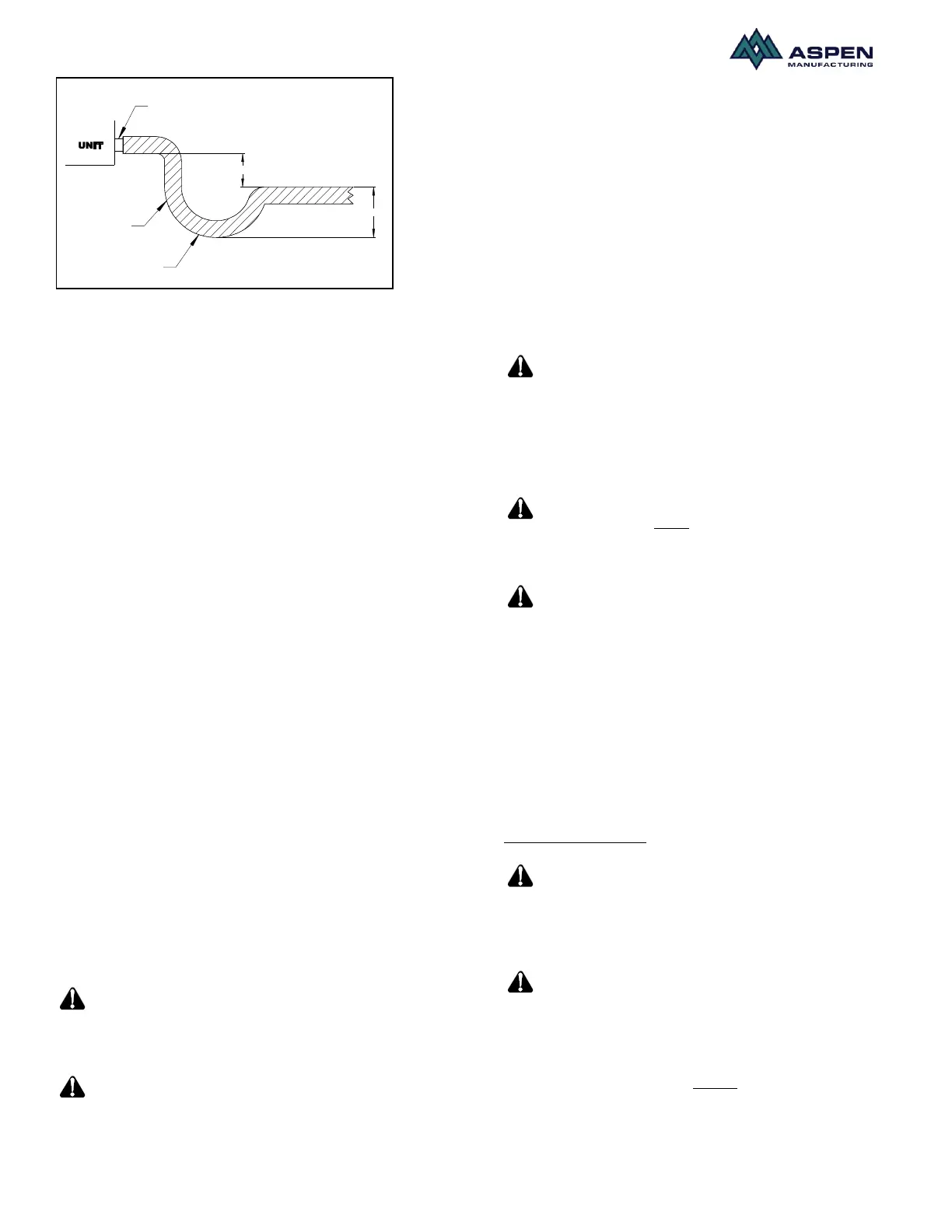
2" MINIMUM
3" MINIMUM
FLEXIBLE
TUBING-HOSE
OR PIPE
A POSITIVE
LIQUID SEAL IS
REQUIRED
DRAIN
CONNECTION
Figure.1. Typical drain line trap set up
Ductwork
Duct systems should be installed in accordance with
standards for air-conditioning systems, National Fire
Protection Association Pamphlet No. 90A or 90B. They
should be sized in accordance with National
Environmental System Contractors Association Manual
K, or whichever is applicable.
On any job, non-flammable flexible collars should be
used for the return air and discharge connections to
prevent transmission of vibration. Although these units
have been specially designed for quiet vibration-free
operation, air ducts can act as soundboards can, if
poorly installed, amplify the slightest vibration to the
annoyance level.
All main supply and return air drops should be properly
size as determined by the designer of the duct system
and should not necessarily be the size of the duct flange
openings of the unit.
When installing a central air return grille in or near the
living space, it is advisable to design the ductwork so
that the grille is not in direct line with the opening in the
unit. One or two elbows and acoustical duct liner will
also assure a quieter installation and system.
It is recommended that wherever supply and return air
sheet metal duct pass through unconditioned areas, they
be insulated to prevent excessive heat loss during
heating operation. When applied in conjunction with
summer air conditioning, sheet metal duct routed
through unconditioned areas should be insulated and
have an outside vapor barrier to prevent formation of
condensation.
Installation
Ensure that the unit is adequately
sized. The tonnage of the outdoor unit should never
exceed the tonnage of this unit.
The coil was manufactured with
dry nitrogen pre-charge. Release the pressure through
the Schrader valve test port prior to installation. If
holding pressure is not present, return coil to distributor
for exchange.
Clean coil fins with degreasing agent or mild detergent
and rinse fins clean prior to installation.
All connection joints should be burr-free and clean. Not
removing the burr and cleaning may increase chances of
a leak. It is recommended to use a pipe cutter to remove
the spun closed end of the suction line.
To avoid damage to grommets (where present), remove
these prior to brazing by sliding over the lines. Use a
quenching cloth or allow the lines to cool before
reinstalling the grommets.
Prior to connecting the water
(hydronic) coil, make sure that the hot water supply is
turned on. Water from the heater could be extremely hot
and might result in burns and other personal injusry
along with equipment damage. Ensure that proper saftey
gear is being used prior to making connections.
Only lead free solder should be
used to connect water (hydronic) coil to the hot water
source.
Some Aspen coils may include a
Schrader valve on the suction manifold. Ensure that the
Schrader valve and valve core (where present) are
protected from heat to prevent leakage.
Metering Device
Aspen coils are available with two kinds of metering
devices a) flowrator or b) TXV. Instructions below are
separated in sections according to the metering device.
Ensure that the applicable section is thoroughly read and
understood.
Flowrator Coils:
Use Piston sizes recommended by
the outdoor unit manufacturer whenever possible. The
piston should be sized according to the capacity of the
outdoor unit.
Failure to install the proper piston
can lead to poor system performance and possible
compressor damage.
During some installations a piston change may be
required. If so the installer MUST change the piston. As
stated earlier, use piston sizes recommended by the
outdoor unit manufacturer. If a sizing chart is not
available, use the piston size chart provided below to
 Loading...