IO-123075 Effective 12-01-11
Counter Flow Installation
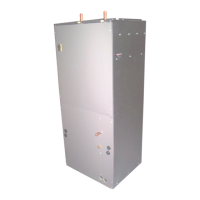
Fig.8. Air Handler parts and changes for Counter flow
• Before positioning the Air Handler in the counter
flow position, remove lower access panels, filter
panel and filter.
• Remove the A-Coil assembly with the horizontal
drain pan; discard the horizontal drain pan (not
required for counter flow application).
• Rotate the Air Handler 180° to the counter flow
position.
• Remove the coil deck and filter channel, rotate
the filter channels 180° and re-attach in the
same location they were removed from.
• Rotate the coil deck 180° and re-attach in the
holes near the center of the cabinet (screws not
provided).
• Slide the A-coil assembly into the cabinet on the
coil deck (without the horizontal drain pan).
Note: Push the coil pan assembly all the way to
the rear of the cabinet until it locks under the
bracket in the rear.
• Place the 3” x 16” counter flow plates at the
outside bottom of the coil as shown in FIG. 9.
• Replace the access panels and filter panel.
Fig.9. Position of plates required in counter flow
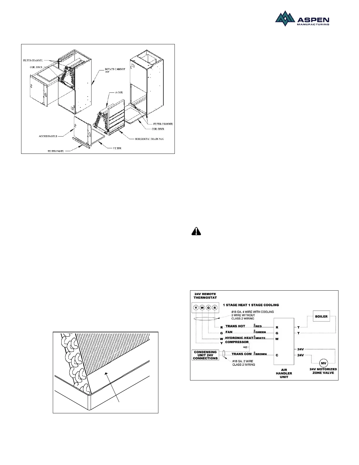
Electrical Installation
These units are designed for single or three phase 120
volts, 60 Hz power supply. Wire selection and wiring
must be in accordance with the National Electric Code
and/or local codes. Unit terminals are designed to
accommodate copper and aluminum wirings. If
aluminum wiring is used; please observe special
precautions relative to sizing, wire connections and
corrosion protection.
Fig.10 shows the typical electrical connections required
for A/C only and heat pump applications.
The unit ships with a micro-processor based board
which controls the electrical functioning of the unit. An
inspection of the controls is recommended prior to start-
up.
Fig.11 provides a schematic of the control board present
in the unit. The units ship from the factory with the
aquastat jumper in the OFF position (right two pins) and
the heating selector in the HW position (right two pins). If
an aquastat is used in the application; the jumper should
be changed to ON position (left two pins).
Note: Terminals T and N located on the top right side
of the board are not intended for field use and should be
left unconnected.
The aquastat (AQ) jumper must be
in the OFF position at all times; except for when an
aquastat is used in the application. If the jumper is
moved to the ON position without installing an aquastat
the blower will not be energized.
When an aquastat is present, the blower will be
energized at the aquastat temperature settings.
Fig 10. Electric connections
On units shipped from factory with a pump installed the
pump will be energized on call for heat.
In units that were shipped without factory installed
pumps, two black wires should be connected to the
boiler terminals T T. In applications where a boiler is
 Loading...