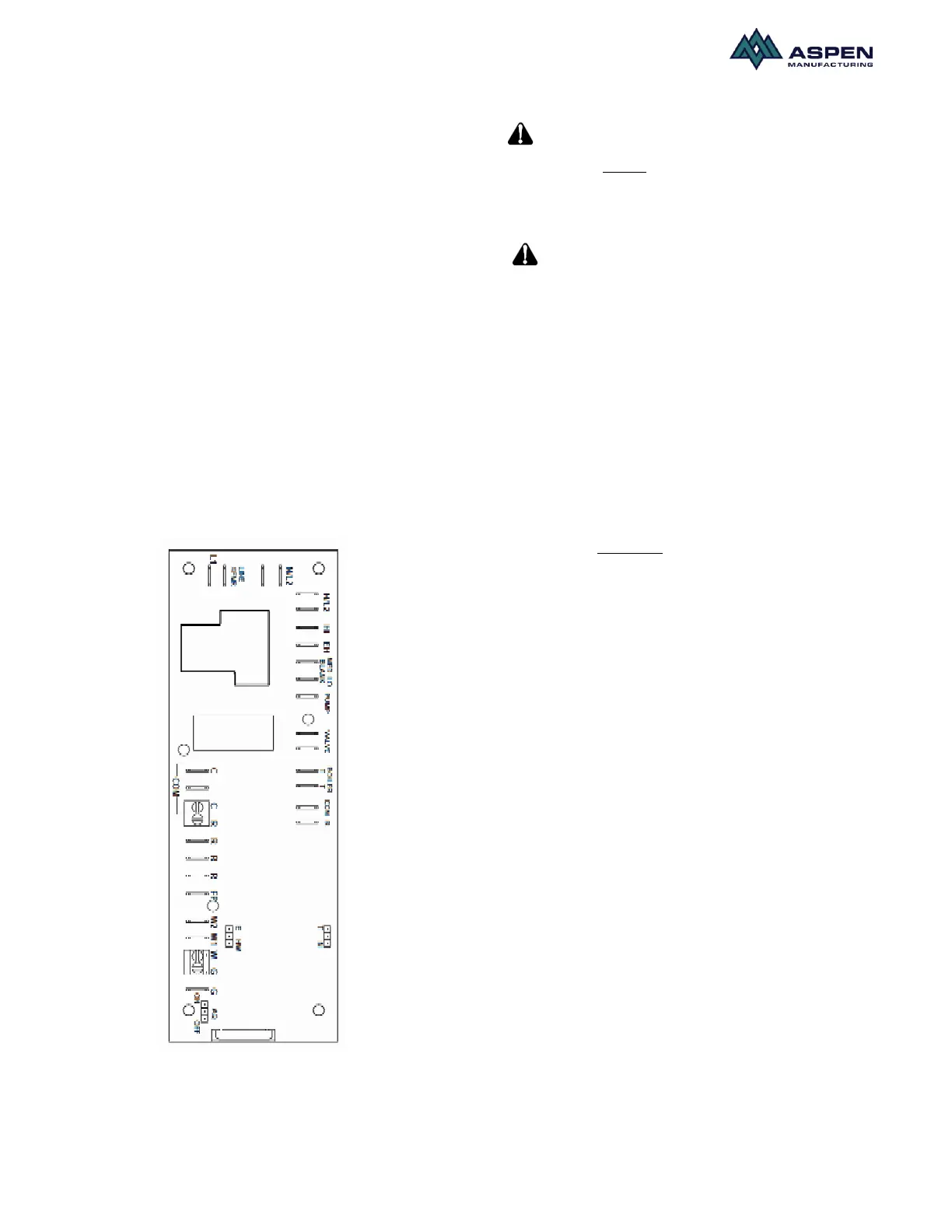
used to provide the hot water supply, these wires shouId
be connected to the boiler. Terminals T T are normally
open dry contacts.
In applications where a valve is used to regulate hot
water supply, the two black wires located on the T T
terminals should be removed and placed on the two
terminals reading “VALVE”. The open ends of the wires
should be connected to the valve according to local
requirments and instructions of the valve manufacturer.
On call for heat, 24V will be sent to the field installed
valve or pump relay.
On call for heat water will circulate through the water
(hydronic) coilfor 60 secs prior to energizing the blower.
After the thermostat is satisfied, the blower will continue
to stay energized for a minimum of 30 sec. This helps
maximize heating efficiency.
The freeze protection sensor is connected to the FP and
R terminals. These are normally open and will close
when the sensor sees 40ºF. The pump stays ON for a
minimum of 30 sec.
The board has an built-in timer which circulates hot
water 6 times a day for 60 sec each time to prevent the
coil from freezing.
Fig.10. Micro-processor control board
Start up
Hot water flowing to the coil
should be in the range of 120º - 180º F. Water at these
temperatures can cause first-degree burns. Use of
proper saftey gear while installing or servicing the
equipment is strongly recommended, as is installation of
a water-tempering valve (for water temperatures of
above 140ºF) to supply lower temperature water to
fixtures in the house. N170L series or equivalent should
be used.
Connect the hydronic coil to the water heater system as
shown in Fig 11. Use flexible piping and insulate all
pipes. Plumbing must be in compliance with state or
local codes (Code CMR248 in Massachusetts). The
units for hydronic heat have different top and heater box
configurations. This configuration is not suitable for
electric heat. DO NOT try to install a hydronic heater in a
unit not equipped for it. Verify connections: hot water to
“in” and cold water to “out”. 7/8” ODstubs are provided
for plumbing connections. Bleed the air flow system
through the bleeder port or optional valve.
Purging The System
1) Open air vent and allow water heater to fill with
water. Close air vent when water heater is full and
all air has been purged.
2) Ignite water heater. Set thermostat on water heater
to 140 degrees.
3) Close the valve on the hot water supply from the
water heater ("A") and open the valve on the cold-
water return to the water heater ("B"). Then open the
air vent in the fan coil. Use a bucket or hose to
discard water during purging process at air bleed
valve. Purge air completely from line.
4) Once air is purged, close return valve ("B") and open
supply valve ("A"). Purge the coil and lines of air
completely.
5) After air is purged from the system and filled with
water, open the return valve ("B") and the supply
valve ("A"). Then close the air vent in the fan coil.
6) Apply power to the fan coil and set the room
thermostat on heat. Raise the temperature setting to
activate the circulating pump
7) Check the pump to ensure proper operation. The
water inlet of the unit should be hot if the water
temperature in the water heater has reached the set
point. If water is not being circulated through the coil
but the pump is running, then open the air bleed
valve in the unit and purge any air left in the system.
 Loading...