8) Adjust the water heater thermostat so that the water
temperature entering the hot water coils is 120 –
180ºF depending on the amount of heat required by
the structure. This is done with the unit energized
and operating long enough for all temperatures to
stabalize.
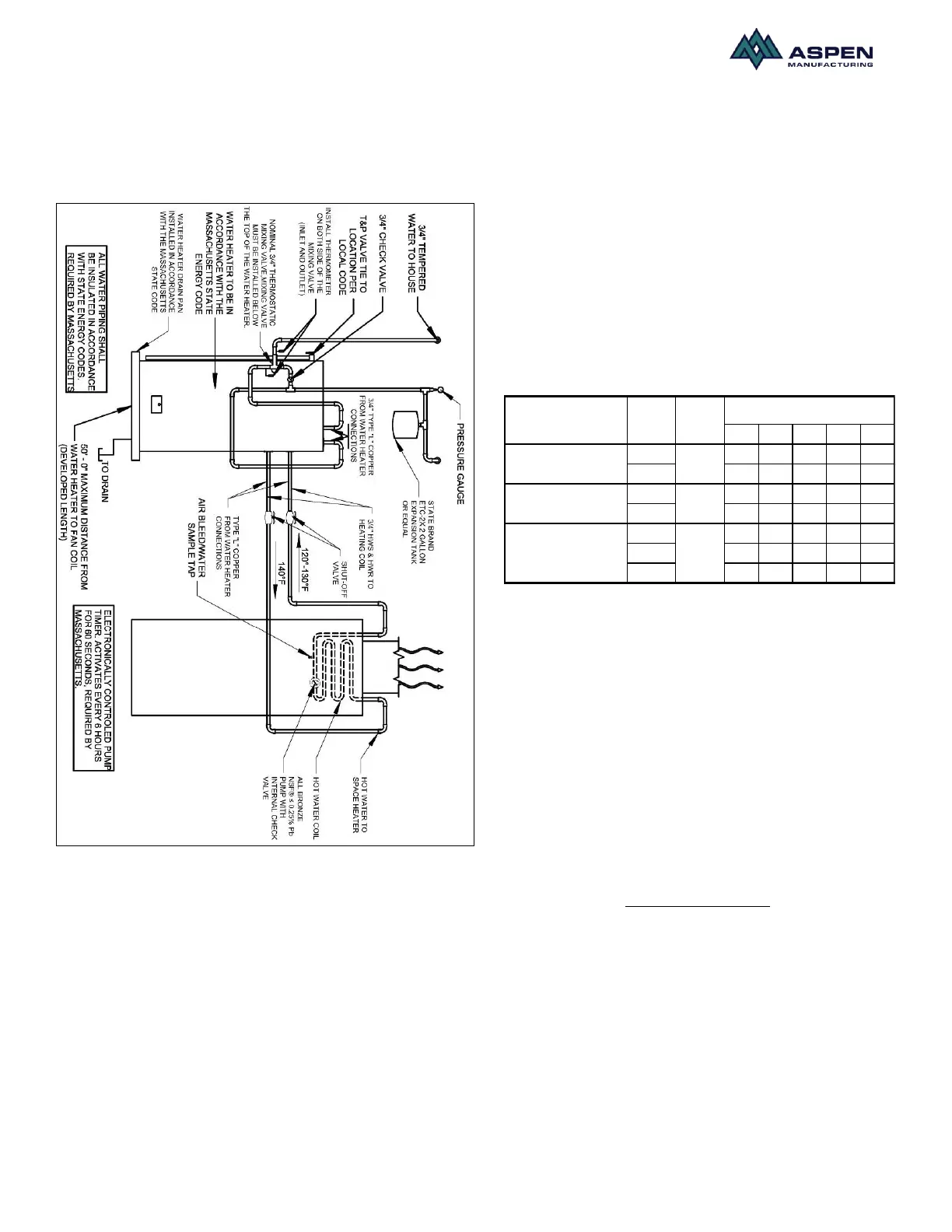
Fig.11. Schematic of hydronic unit set up
After all connections are made, start-up and check-up of
the unit must be performed before proper evaluation of
the entire system can be made. Make sure that heat
anticipator is properly set as noted on thermostat
instructions.
Load requirements can vary in each residence and it
may be necessary for the installer or homeowner to
make slight adjustments to the heat anticipator setting
for longer or shorter cycles. It is recommended to
change the setting no more than plus or minus 0.05
amps at a time. Greater changes can cause the unit to
rapid cycle or remain on excessively. To properly check
the unit's operation, the installer should have an
electrical current measuring device (0-10 amp Amprobe,
Fluke), air pressure measuring device (0-1.0 in slope
gauge), and a temperature-measuring device (0-200ºF
thermometer).
Install the Amprobe to measure blower current, the slope
gauge to measure static air pressure at the units and the
temperature device to measure unit supply and return air
temperature. Before taking measurements, be sure that
all registers, grilles and dampers are open or set to their
proper positions. Be sure that clean filters are in place.
Temperature measuring device must be installed to
obtain average temperature at both inlet and outlet. For
outlet, measure temperature of each main trunk at a
location far enough away to avoid heater radiation and
read the average temperatures. Table 2 below shows
the CFM that should be achieved at various external
static pressures
Table 2. CFM delivered at various external statics
Electric Heat Controls
• Turn on power supply. Set thermostat fan switch to
on. Set the cooling indicator to maximum, heating to
minimum. System switch may be on heat or cool.
Check slope gauge measurement against
appropriate air flow chart. Make damper, register
and motor speed adjustments to obtain required
airflow.
• Set thermostat fan switch to auto, system to heat
and thermostat heating indicator to maximum heat.
Blower should start and all heat be energized.
• Check air flow using temperature rise method.
NOTE: BTUH output should be computed by VOLT x
AMPS x 3.4 = BTUH OUTPUT. Since line volt can vary,
do not use nameplate rating to determine output.
Operation and Maintainance
Below are brief descriptions of the key components of
the unit and installation. This manual only provides a
general idea of the components and recommended
 Loading...