IO-123075 Effective 12-01-11
size the required piston. The size of the piston is
stamped on the piston body. Use table 1 to determine
pizton size when matching coil with an outdoor unit with
a different nominal capacity than the coil.
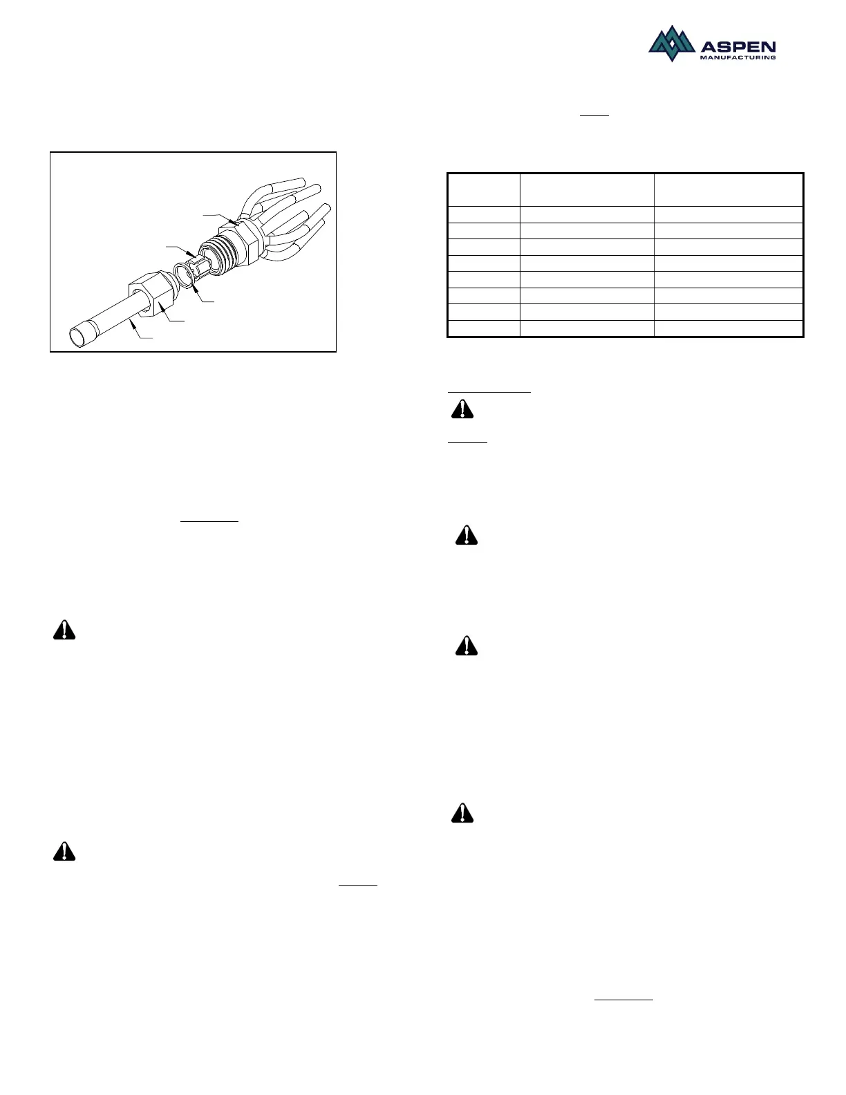
PISTON
DISTRIBUTOR
TAIL PIECE
13/16" NUT
TEFLON O-RING
Figure.2. Flowrator assy components
Instruction for piston change
1) Turn the 13/16 nut once to release any residual
pressure in the coil.
2) After ensuring that the coil is free of any residual
pressure, disassemble the flowrator body
completely using two wrenches. Distortion of the
feeder tubes SHOULD be avoided.
3) The wrench used to clasp the nut should be
turned in a counter-clockwise direction to
unscrew the nut.
4) Slide the 13/16 nut over the line set and
separate the two halves of the flowrator.
Pay close attention to the Teflon
O-ring. Be sure to replace the O-ring to attain a proper
seal. (The Teflon O-ring is located between the two
halves of the flowrator). Refer to Fig 2 for a schematic of
the flowrator.
5) Pull the piston out using a small wire or pick.
Verify the piston size (size is typically stamped
on the body of the piston). If a different piston
size is required by the outdoor unit manufacturer
replace the piston using the small wire provided
with the piston kit.
Pay close attention to the piston
orientation. The pointed end of the piston MUST go
into the distributor body/towards the coil. Failure to
ensure this orientation will cause the piston to be
bypassed during operation which might damage the
outdoor unit.
6) Assemble the two halves correctly and ensure
that the white Teflon O-ring is present between
the two halves.
7) Slide the 13/16 nut onto the distributor body.
8) Tighten the nut to a torque of approximately 10-
30 ft-lbs. Do NOT over tighten the nut. This will
hamper the piston movement during operation.
9) Slide the grommet back to position to prevent air
leakage.
Table.1. Piston Size Chart
TXV Coils:
The sensing bulb and TXV body
MUST be protected from overheating during brazing.
The sensing bulb and TXV body must be covered using
a quench cloth or wet cloth when brazing. Pointing the
brazing flame away from the valve and sensing bulb
provide partial protection only.
Ensure that the TXV selected is
compatible with the refrigerant used in the outdoor
system (R22 or R410A). TXV caps are painted green for
R22 or pink for R410A. In absence of color, the caps will
be marked with the compatible refrigerant.
The valves should be sized
according to the capacity of the outdoor unit. Failure to
install the right valve can lead to poor performance and
possible compressor damage.
TXV Bulb Mounting
The orientation and location of the TXV bulb has a major
influence on the system performance.
Ensure that the TXV bulb is in
direct contact with the suction/vapor line. Gap between
the bulb and tube should be avoided. Failure to eliminate
gaps will impair the proper functioning of the TXV valve.
It is recommended that the TXV bulb be installed parallel
to the ground (in a horizontal plane). The bulb position
should be above and between 4 o’clock and 8 o’clock.
Fig. 3 shows the recommended position for the TXV bulb
installation in the horizontal plane.
The TXV sensing bulb SHOULD be mounted using the
metal clamp provided. In order to obtain a good
 Loading...