2424
2424
24
ASRock ALiveXFire-eSATA2 Motherboard
EnglishEnglish
EnglishEnglish
English
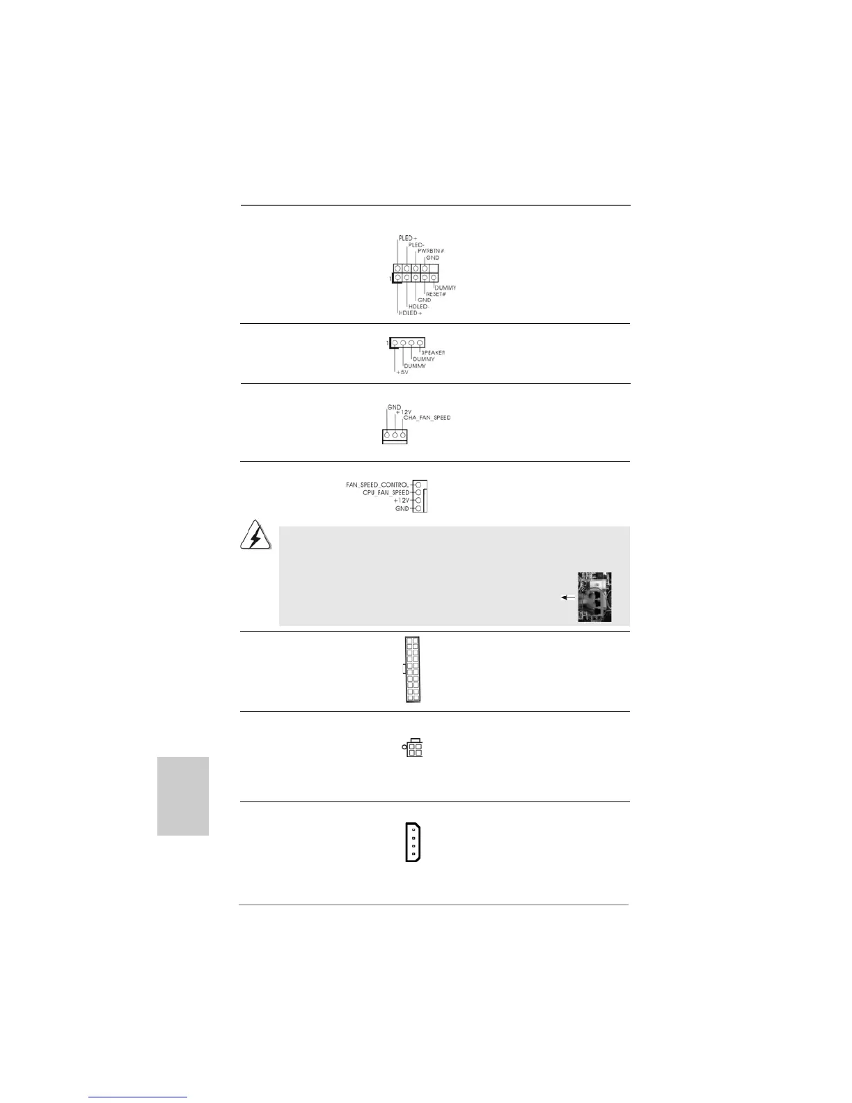
Chassis Speaker Header Please connect the chassis
(4-pin SPEAKER 1) speaker to this header.
(see p.2 No. 24)
Chassis Fan Connector Please connect a chassis fan
(3-pin CHA_FAN1) cable to this connector and
(see p.2 No. 22) match the black wire to the
ground pin.
CPU Fan Connector Please connect the CPU fan
(4-pin CPU_FAN1) cable to this connector and
(see p.2 No. 3) match the black wire to the
ground pin.
Though this motherboard provides 4-Pin CPU fan (Quiet Fan) support, the 3-Pin
CPU fan still can work successfully even without the fan speed control function.
If you plan to connect the 3-Pin CPU fan to the CPU fan connector on this
motherboard, please connect it to Pin 1-3.
3-Pin Fan Installation
Pin 1-3 Connected
ATX Power Connector Please connect an ATX power
(20-pin ATXPWR1) supply to this connector.
(see p.2 No. 4)
ATX 12V Power Connector Please note that it is necessary
(4-pin ATX12V1) to connect a power supply with
(see p.2 No. 2) ATX 12V plug to this connector.
Failing to do so will cause power
up failure.
SLI/XFIRE Power Connector It is not necessary to use this
(4-pin SLI/XFIRE_POWER1) connector, but please connect it
(see p.2 No. 33) with a hard disk power connecor
when two graphics cards are
plugged to this motherboard at
the same time.
4
3
2
1
SLI/XFIRE_POWER1
System Panel Header This header accommodates
(9-pin PANEL1) several system front panel
(see p.2 No. 23) functions.
 Loading...