Super
I/O
`
PCI
EXPRESS
USB2.0
CMOS
BATTERY
ATXPWR1
SOCKET AM2
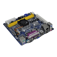
AM2NF6G-VSTA
CD1
NVIDIA
GeForce 6100 /
nForce 405
Chipset
ATX12V1
PS2_USB_PW1
1
COM1
IDE1
FSB800
DDRII_1 (64/72 bit, 240-pin module)
DDRII_2 (64/72 bit, 240-pin module)
FSB800
DDRII_3 (64/72 bit, 240-pin module)
DDRII_4 (64/72 bit, 240-pin module)
PCIE1
PCI1
PCI2
4Mb
BIOS
LAN
PHY
AUDIO
CODEC
SATAII_1
SATAII_2
1
CLRCMOS1
1
DDRII800
Dual Core CPU
FSB1GHz
Dual Channel
ATA133
SATAII
7.1CH HD
RAID
CPU_FAN1
HDLED RESET
PLED PWRBTN
1
PANEL1
CHA_FAN1
SPEAKER1
1
USB4_5
1
IR1
FLOPPY1
GAME1
1
HD_AUDIO1
1
RoHS
24.4cm (9.6-in)
24.4cm (9.6-in)
6
7
1
2
4
3
5
8
9
10
11
12
13
14
15
16
17
18
19
20
21
22
23
24
25
26
27
28
29
PCIE2
1
USB6_7
1
HDMR1
USB 2.0
T: USB 2
B: USB3
PARALLEL PORT
VGA1
PS2
Mouse
PS2
Keyboard
Top:
REAR SPK
Center:
SIDE SPK
Bottom:
CTR BASS
Top:
LINE IN
Center:
FRONT
Bottom:
MIC IN
USB 2.0
T: U SB 0
B: USB1
Top:
RJ-45
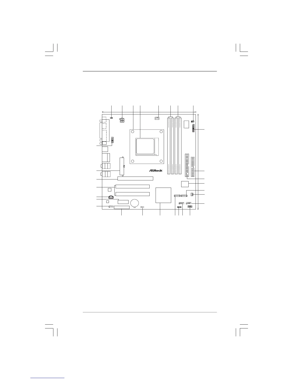
1 PS2_USB_PW1 Jumper 15 USB 2.0 Header (USB6_7, Blue)
2 ATX 12V Power Connector (ATX12V1) 16 System Panel Header (PANEL1)
3 CPU Heatsink Retention Module 17 USB 2.0 Header (USB4_5, Blue)
4 AM2 940-Pin CPU Socket 18 Chassis Speaker Header (SPEAKER 1)
5 CPU Fan Connector (CPU_FAN1) 19 Secondary SATAII Connector (SATAII_2, Red)
6 2 x 240-pin DDRII DIMM Slots 20 NVIDIA Single Chip
(Dual Channel A: DDRII_1, DDRII_2; Yellow) 21 Clear CMOS Jumper (CLRCMOS1)
7 2 x 240-pin DDRII DIMM Slots 22 HDMR Slot (HDMR1)
(Dual Channel B: DDRII_3, DDRII_4; Orange) 23 Front Panel Audio Header (HD_AUDIO1)
8 Infrared Module Header (IR1) 24 PCI Express x1 Slot (PCIE2)
9 Game Port Header (GAME1) 25 Internal Audio Connector: CD1 (Black)
10 Floppy Connector (FLOPPY1) 26 PCI Slots (PCI1- 2)
11 Primary IDE Connector (IDE1, Blue) 27 PCI Express Graphics Slot (PCIE1)
12 Flash Memory 28 ATX Power Connector (ATXPWR1)
13 Primary SATAII Connector (SATAII_1, Red) 29 Serial Port Connector (COM1)
14 Chassis Fan Connector (CHA_FAN1)
 Loading...