EasyManuals Logo

ASROCK B75M-ITX User Manual

ASROCK B75M-ITX
57 pages
To Next Page IconTo Next Page
To Previous Page IconTo Previous Page
Page #29 background imageLoading...
Page #29 background image
29
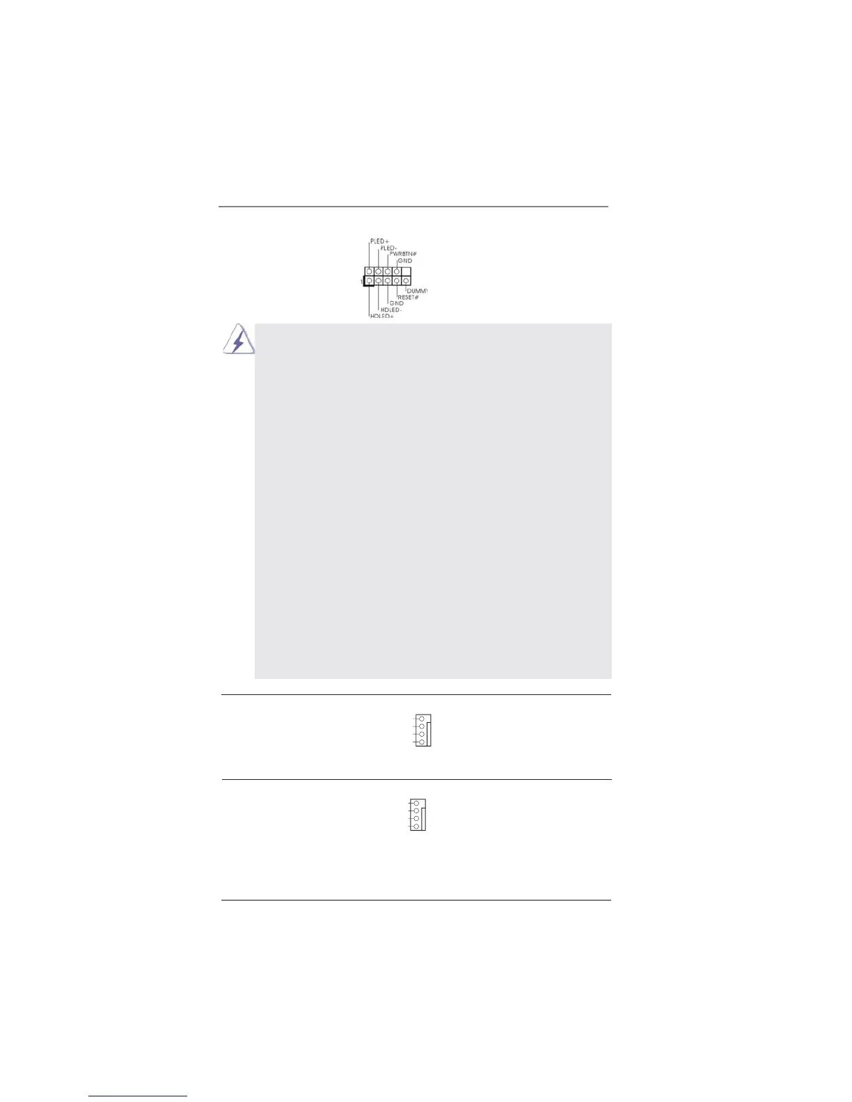
System Panel Header This header accommodates
(9-pin PANEL1)
several system front panel
(see p.13, No. 8)
functions.
Connect the power switch, reset switch and system status indicator on the
chassis to this header according to the pin assignments below. Note the
positive and negative pins before connecting the cables.
PWRBTN (Power Switch):
Connect to the power switch on the chassis front panel. You may con gure
the way to turn off your system using the power switch.
RESET (Reset Switch):
Connect to the reset switch on the chassis front panel. Press the reset
switch to restart the computer if the computer freezes and fails to perform a
normal restart.
PLED (System Power LED):
Connect to the power status indicator on the chassis front panel. The LED
is on when the system is operating. The LED keeps blinking when the sys-
tem is in S1/S3 sleep state. The LED is off when the system is in S4 sleep
state or powered off (S5).
HDLED (Hard Drive Activity LED):
Connect to the hard drive activity LED on the chassis front panel. The LED
is on when the hard drive is reading or writing data.
The front panel design may differ by chassis. A front panel module mainly
consists of power switch, reset switch, power LED, hard drive activity LED,
speaker and etc. When connecting your chassis front panel module to this
header, make sure the wire assignments and the pin assign-ments are
matched correctly.
Chassis Fan Connector Please connect the chassis fan
(4-pin CHA_FAN1)
cable to the connector and
(see p.13, No. 17)
match the black wire to the
ground pin.
FAN_SPEED_CONTROL
GND
+12V
CHA_FAN_SPEED
CPU Fan Connectors Please connect the CPU fan
(4-pin CPU_FAN1)
cable to the connector and
(see p.13, No. 16)
match the black wire to the
ground pin.
4
3
2
1
GND
+12V
CPU_FAN_SPEED
FAN_SPEED_CONTROL

Table of Contents

Other manuals for ASROCK B75M-ITX

Questions and Answers:

Question and Answer IconNeed help?

Do you have a question about the ASROCK B75M-ITX and is the answer not in the manual?

ASROCK B75M-ITX Specifications

General IconGeneral
ECCNo
Non-ECCYes
Memory voltage1.5 V
Memory channelsDual-channel
Memory slots typeDIMM
Number of memory slots2
Supported memory typesDDR3-SDRAM
Maximum internal memory16 GB
Supported memory clock speeds1066, 1333, 1600 MHz
Supported memory module capacities1GB, 2GB, 4GB, 8GB
System bus rate5 GT/s
Processor socketLGA 1155 (Socket H2)
Processor manufacturerIntel
Compatible processor seriesIntel Core i3, Intel Core i5, Intel Core i7
Maximum number of SMP processors1
Number of SATA II connectors3
Number of Parallel ATA connectors0
HDMI version1.4a
Headphone outputs5
USB 2.0 ports quantity4
Audio chipRealtek ALC892
Cooling typePassive
CertificationFCC, CE, WHQL, ErP/EuP Ready
Component forPC
Power source typeATX
Motherboard chipsetIntel B75
PC health monitoringCPU, FAN, Temperature
Audio output channels7.1 channels
Motherboard form factormini ITX
Compatible operating systemsWindows 7, Vista, XP 32/64-bit
Supported storage drive interfacesSATA II, SATA III
Cables includedSATA
Graphics cardHD Graphics
OpenGL version3.2
DirectX version11
Maximum resolution2048 x 1536 pixels
Maximum graphics card memory1760 MB
Parallel processing technology supportNot supported
PCI Express slots version3.0
PCI Express configurations1x16
LAN controllerRealtek RTL8111E
Networking featuresGigabit LAN
Ethernet interface typeGigabit Ethernet
BIOS typeEFI AMI
ACPI version1.1
BIOS memory size64 Mbit
Weight and Dimensions IconWeight and Dimensions
Width170 mm

Related product manuals