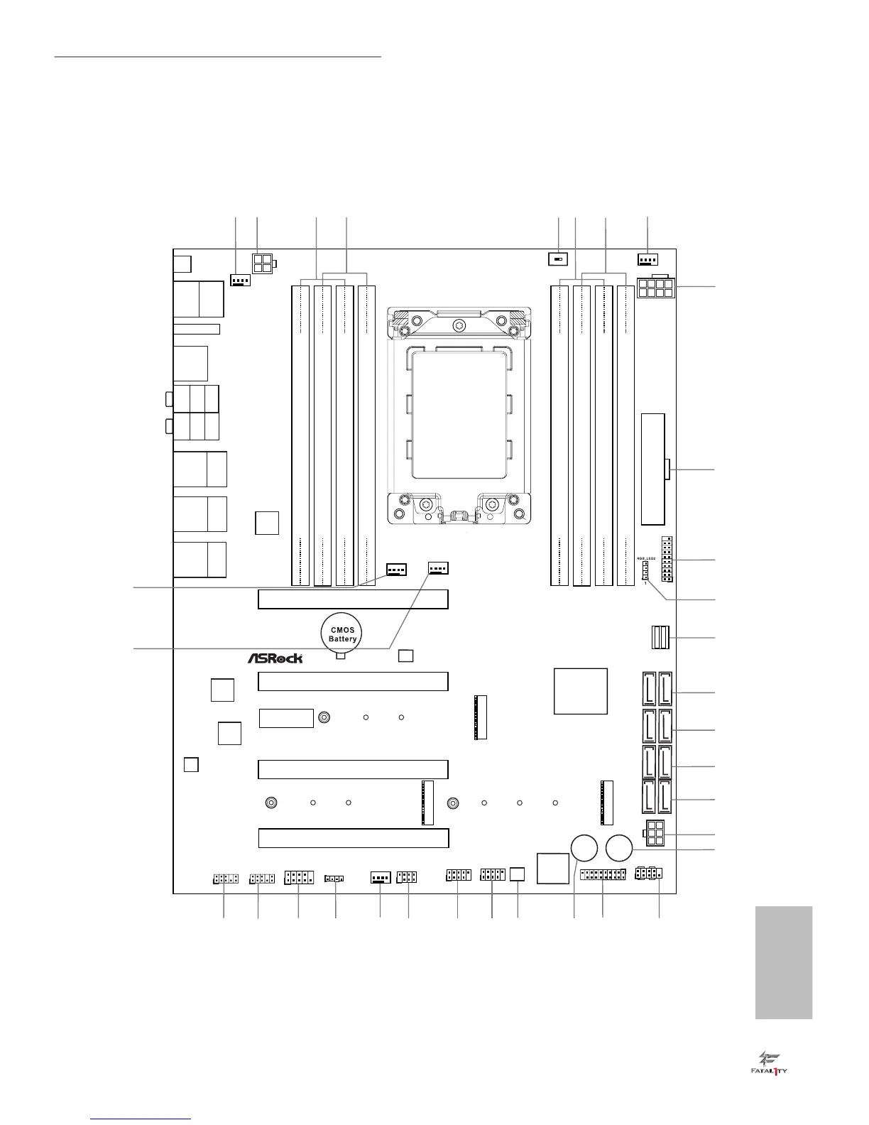
ATXPWR1
X399 Gaming
FATAL TY1
AMD
X399
ATX 12V1
LAN
LAN
LAN
PCIE2
Top:
Central/Bass
Center:
REAR SPK
Top:
LINE IN
Center:
FRONT
Bottom:
Optical
SPDIF
Bottom:
MIC IN
PCIE4
HDLED RESET
PLED PWRBTN
PANEL1
1
USB_3_4
1
1
USB_1_2
1
HD_AUDIO1
1
HD_AUDIO_RA1
PCIE5
SATA3 _5 _6
SATA3 _3 _4
PCIE3
CPU_FAN1
RoHS
10
9
13
14
15
16
SATA3 _1 _2
17
24
25 2331 2930
CLRC
BTN1
BIOS
_FB1
SATA3 _7 _8
2
5
1
8
DDR4_D1 (64 bit, 288-pin module)
DDR4_D2 (64 bit, 288-pin module)
DDR4_C1 (64 bit, 288-pin module)
DDR4_C2 (64 bit, 288-pin module)
4
3
2627 20
21
M2_WIFI_1
CHA_FAN2
CHA_FAN1
22
33
32
DDR4_A2 (64 bit, 288-pin module)
DDR4_A1 (64 bit, 288-pin module)
DDR4_B2 (64 bit, 288-pin module)
DDR4_B1 (64 bit, 288-pin module)
7
6
TR4 Socket
(4094 pins)
USB3_11_12
Dr.
Debug
Reset
Power
1
SPK_PLED1
Top:
RJ-45
USB 3.1
T: USB31_TA_1
B: USB31_TC_1
AUDIO
CODEC
11
12
1
1
USB3_9_10
18
19
RGB_LED1
1
28
Top:
RJ-45
USB 3.0
T: USB7
B: USB8
Top:
RJ-45
USB 3.0
T: USB3
B: USB4
USB 3.0
T: USB5
B: USB6
PCIE1
CHA_FAN3/
W_PUMP
CPU_OPT/
W_PUMP
USB 3.0
T: USB1
B: USB2
PS2
Keybo ard
/Mous e
ATX 12V2
GFX_12V1
BIOS
ROM
COM1
1
U2_1
M2_2
M2_1
M2_3
MOS_PROCHOT1
ON
OFF
 Loading...