English
32
2.10 HDD Saver Cable Installation Guide
The HDD Saver Connector on this motherboard allows you to switch on and off the
connected HDDs via soware when needed. is design secures more privacy, saves more
energy, and extends the HDDs' lifespans. Please follow the steps below to install the HDD
Saver Cable.
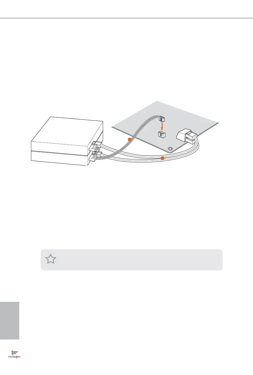
Connection Diagram
*e diagram shown here is for reference only.
1. Connect one end of the HDD Saver Cable to the HDD Saver Connector (SATA_
PWR_1) placed near the SATA ports. en connect the SATA power connector(s) to
your SATA HDD(s).
* e HDD Saver Connector supports up to two SATA HDDs.
2. Connect one end of the SATA data cable to a SATA port on the motherboard. en
connect the other end to your SATA HDD(s).
2
1
HDD Saver Cable
SATA data cable
For the soware conguration, please refer to the section 3.2 “F-Stream” in this user
manual.

 Loading...