24
ASRock H67M-ITX/HT / H67M-ITX Motherboard
English
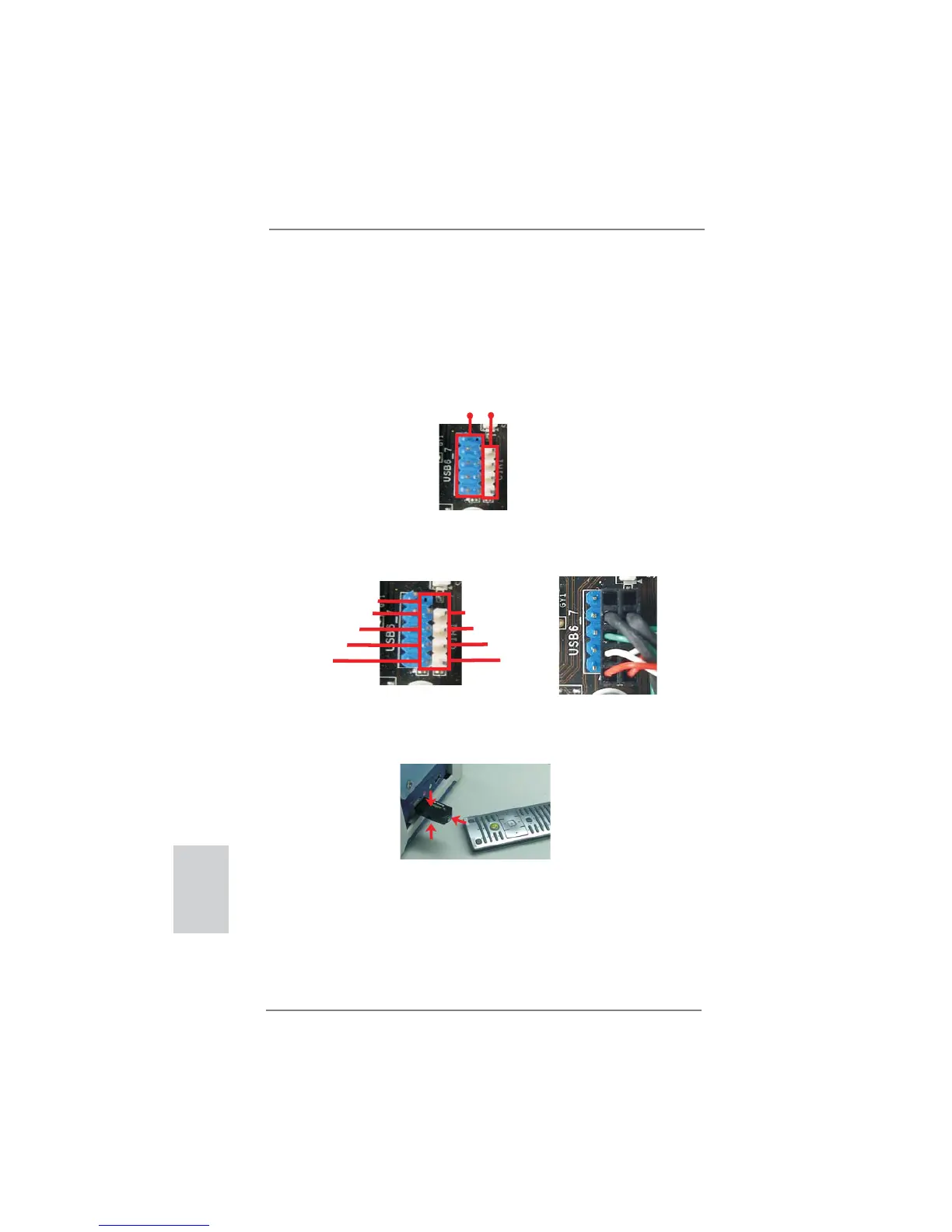
2.6 Remote Receiver Installation Guide
This motherboard is equipped with a 4-pin CIR header (CIR1, see page 2/3,
No. 9), which is used to connect the Remote Receiver. Please refer to below
procedure for installing the Remote Receiver.
1. Find the CIR header located next to the USB 2.0 header
(USB8_9, see page
2/3, No. 8) on this motherboard.
2. Connect the front USB cable to the USB 2.0 header (as below, pin 1-5) and the
CIR header. Please make sure the wire assignments and the pin assignments are
matched correctly.
3. Install the Remote Receiver to the front USB port. If the Remote Receiver cannot
successfully receive the infrared signals from the Remote Controller, please try to
install it to the other front USB port.
* Only one of the front USB port can support CIR function. When the CIR function is enabled,
the other port will remain USB function.
* The Remote Receiver is used for front USB only. Please do not use the rear USB bracket
to connect it on the rear panel. The Remote Receiver is able to receive the multi-direction
infrared signals (top, down and front), which is compatible with most of the chassis on the
market.
* The Remote Receiver does not support Hot-Plug function. Please install it before you boot the
system.
USB 2.0 header (9-pin, blue) CIR header (4-pin, white)
1
2
4
3
5
USB_PWR
P-
P+
GND
ATX+5VSB
IRRX
IRTX
GND
DUMMY
 Loading...