17
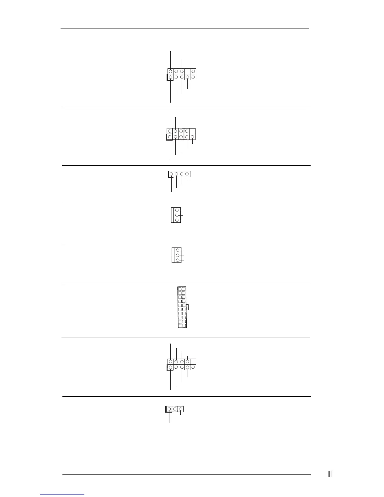
Front panel audio connector This is an interface for front
(9-pin AUDIO1) panel audio cable that allows
(see p.7 item 26) convenient connection and
control of audio devices.
System panel connector This connector accommo-
(9-pin PANEL1) dates several system front
(see p.7 item 17) panel functions.
External speaker connector This connector allows you to
(4-pin SPEAKER 1) attach to an external speaker.
(see p.7 item 15)
Chassis fan connector Connect the fan cable to the
(3-pin CHA_FAN1) connector matching the black
(see p.7 item 14) wire to the ground pin.
CPU fan connector Connect the fan cable to the
(3-pin CPU_FAN1) connector matching the black
(see p.7 item 3) wire to the ground pin.
ATX power connector Connect an ATX power
(20-pin ATXPWR1) supply to the connector.
(see p.7 item 7)
Serial port connector This COM1 header supports
(9-pin COM1) a serial port module.
(see p.7 item 23)
Power LED Connector Please connect a 3-pin power
(3-pin PWR_LED1) LED cable to this connector.
(see p.7 item. 16)
GND
PWRBTN#
PLED-
PLED+
DUMMY
RESET#
GND
HDLED+
HDLED-
1
+5V
DUMMY
DUMMY
SPEAKER
1
GND
+12V
CHA_FAN_SPEED
GND
+12V
CPU_FAN_SPEED
CCTS#1
DDSR#1
DDTR#1
RRXD1
DDCD#1
TTXD1
GND
RRTS#1
RRI#1
1
GND
GND
+5VA
BACKOUT-R
BACKOUT-L
AUD-OUT-L
AUD-OUT-R
MIC-POWER
MIC
1
1
PLED+
PLED+
PLED-