31
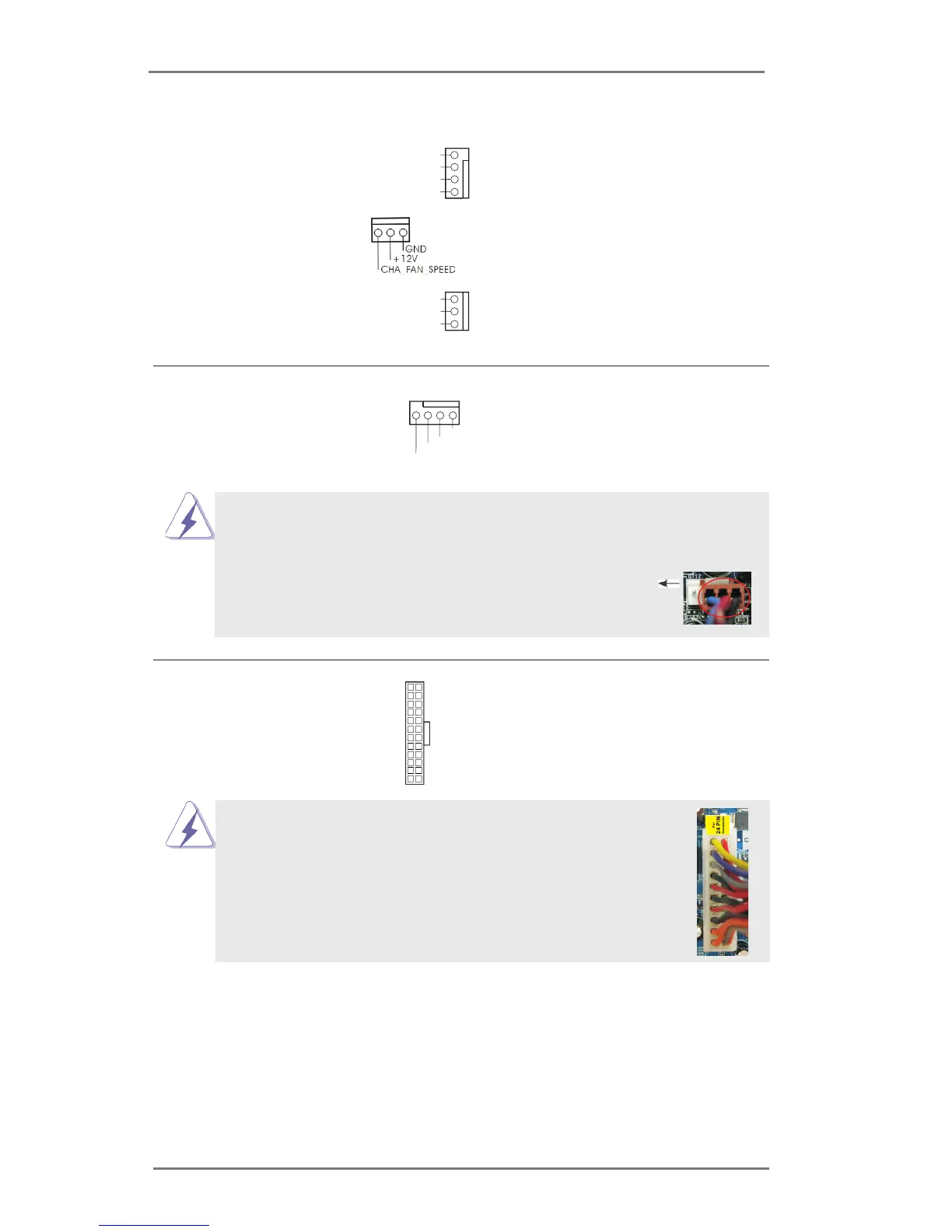
Chassis and Power Fan Connectors Please connect the fan cables
(4-pin CHA_FAN1)
to the fan connectors and match
(see p.13, No. 33)
the black wire to the ground pin.
(3-pin CHA_FAN2)
(see p.13, No. 13)
(3-pin PWR_FAN1)
(see p.13, No. 32)
ATX Power Connector Please connect an ATX power
(24-pin ATXPWR1)
supply to this connector.
(see p.13, No. 5)
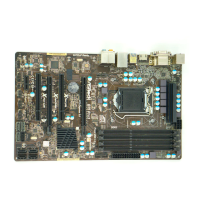
20-Pin ATX Power Supply Installation
Though this motherboard provides 24-pin ATX power connector,
it can still work if you adopt a traditional 20-pin ATX power supply.
To use the 20-pin ATX power supply, please plug your
power supply along with Pin 1 and Pin 13.
12
1
24
13
12
1
24
13
GND
+12V
PWR_FAN_SPEED
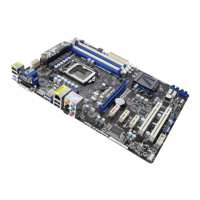
CPU Fan Connectors Please connect the CPU fan
(4-pin CPU_FAN1)
cable to the connector and
(see p.13, No. 1)
match the black wire to the
ground pin.
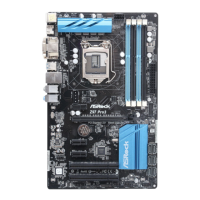
Though this motherboard provides 4-Pin CPU fan (Quiet Fan) support, the 3-Pin
CPU fan still can work successfully even without the fan speed control function.
If you plan to connect the 3-Pin CPU fan to the CPU fan connector on this
motherboard, please connect it to Pin 1-3.
3-Pin Fan Installation
Pin 1-3 Connected
FAN_SPEED_CONTROL
GND
+12V
CHA_FAN_SPEED
4 3 2 1
GND
+12V
CPU_FAN_SPEED
FAN_SPEED_CONTROL