22
English
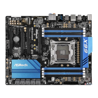
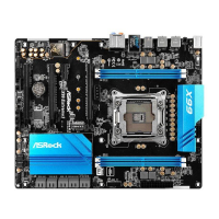
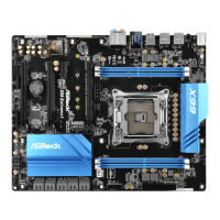
Power LED Header
(3-pin PLED1)
(see p.6, No. 19)
Please connect the chassis
power LED to this header
to
indicate the system’s
power status.
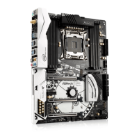
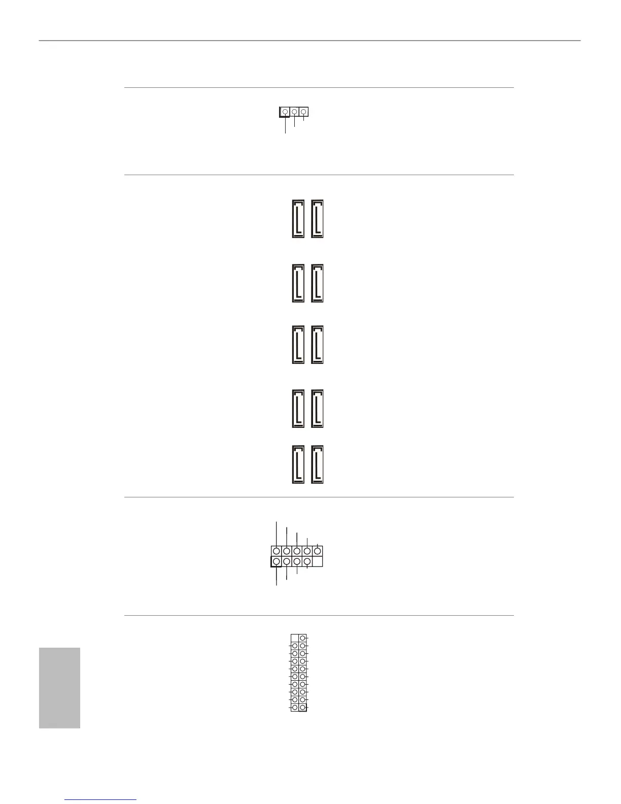
Serial ATA3 Connectors
(S_SATA3_0_1:
see p.6, No. 12)
(S_SATA3_2_3:
see p.6, No. 13)
(SATA3_0_1:
see p.6, No. 16)
(SATA3_2_3:
see p.6, No. 15)
(SATA3_4_5:
see p.6, No. 14)
ese ten SATA3
connectors support SATA
data cables for internal
storage devices with up
to 6.0 Gb/s data transfer
rate. If the eSATA port
on the rear I/O has been
connected, the internal
S_SATA3_3 will not
function. If the Ultra M.2
Socket has been occupied,
the internal S_SATA3_2
will not function.
* RAID is supported on
SATA3_0 ~ SATA3_5
ports only.
USB 2.0 Headers
(9-pin USB5_6)
(see p.6, No. 28)
(9-pin USB7_8)
(see p.6, No. 27)
Besides four USB 2.0 ports
on the I/O panel, there
are two headers on this
motherboard. Each USB
2.0 header can support
two ports.
USB 3.0 Header
(19-pin USB3_5_6)
(see p.6, No. 9)
Besides four USB 3.0
ports on the I/O panel,
there is one header on this
motherboard. is USB
3.0 header can support
two ports.
 Loading...