ASRock H61TM-ITX Motherboard
13
English
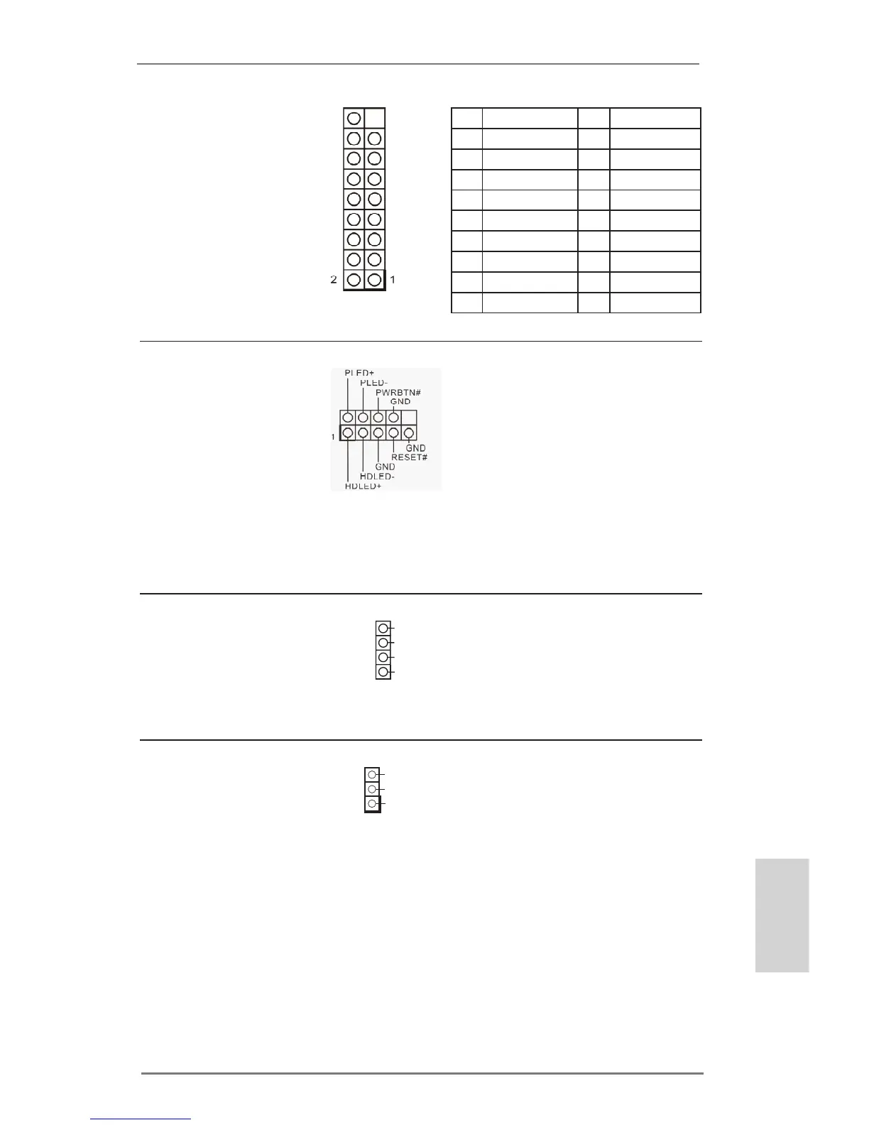
System Panel Header
(9-pin PANEL1)
(see p.2, No. 12)
Analog Surround
Audio Header
(17-pin HD_AUDIO2)
(see p.2, No. 27)
Connect the power switch,
reset switch and system sta-
tus indicator on the chassis
to this header according to
the pin assignments below.
Note the positive and nega-
tive pins before connecting
the cables.
PIN Signal Name PIN Signal Name
18 SENSE 17 KEY
16 LFE 15 A_GND
14 A_GND 13 Center
12 Surr_Rear_R 11 A_GND
10 A_GND 9 Surr_Rear_L
8 Surr_Side_R 7 A_GND
6 A_GND 5 Surr_Side_L
4 Front_R 3 A_GND
2 A_GND 1 Front_L
Power LED Header
(3-pin PLED1)
(see p.2, No. 11)
3W Audio AMP Output
Wafer Header
(4-pin SPEAKER1)
(see p.2, No. 28)
Please connect the chassis
speaker to this header.
Please connect the chassis
power LED to this header
to
indicate system power
status. The LED is on when
the system is operating. The
LED keeps blinking in S1/S3
state. The LED is off in S4
state or S5 state (power off).
Front_L+
Front_R-
1
Front_R+
Front_L-
 Loading...