Do you have a question about the Assa Abloy Aperio AH30 and is the answer not in the manual?
Provides necessary info for planning and performing Aperio communication hub mechanical installation.
Covers information and instructions for complete mechanical installation of Aperio online products.
States that the manual is usable for all versions of Aperio communication hubs.
Informs that products included in the manual may not be available on all markets.
Notes that Aperio support may vary depending on the hub used and integration level.
Lists key terms like EAC, DIP, and RFID with their definitions for clarity.
Lists related documents such as the Quick Installation Guide and Programming Application Manual.
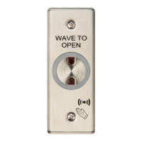
Explains the user interaction flow from card swipe to lock access decision via the EAC system.
Describes the software used for configuring door installations on a laptop via a USB radio device.
Refers to the Programming Application manual for regulatory and security details.
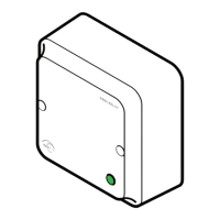
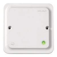
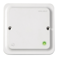
Details the four communication hub types (AH15, AH20, AH30, AH40) and their interfaces.
Discusses factors affecting radio link stability and the need to evaluate installation sites for interference.
Provides general guidelines for optimal placement of communication hubs for stable radio links.
Guidelines for selecting installation places and connecting AH15 hubs to power supply.
Shows typical installations for AH15 hubs with E-cylinder locks for good radio link quality.
Provides examples for AH15 hubs with non-cylinder locks, focusing on achieving good radio link quality.
Guidelines for installing AH20/30/40 hubs, focusing on reliable radio link establishment.
Illustrates typical installations for AH20/30/40 hubs for optimal radio link quality in various scenarios.
Details placement options for AH15 hubs with E-cylinder locks, ensuring range and alignment for radio link.
Provides placement guidance for AH15 hubs with non-cylinder locks, recommending wall mounting.
Details mounting options for AH20/30/40 hubs, considering antenna type and environment for reliable link.
Explains the radio coverage pattern for external antennas and its range limitations.
Details default configuration of AH15 hubs using the RS-485 interface, including DIP switches and connections.
Explains the functionality of DIP switches for selecting EAC addresses and activating pairing modes.
Details RS-485 bus settings for daisy chain and star configurations, including termination requirements.
Explains how to connect the RS-485 bus using twisted-pair cables and notes bus length limits.
Details the voltage and current requirements for powering the communication hub.
Details configuration and connection for AH15 hubs using the Wiegand interface.
Explains DIP switch settings for Wiegand interface, including default configuration and LED signal logic.
Details Wiegand signals and their connections on the AH15 communication hub.
Specifies voltage and current requirements for powering the AH15 communication hub.
Details configuration and connection for AH20 hubs using the Wiegand interface.
Explains DIP switch settings for AH20 Wiegand interface, including default configuration and LED signal logic.
Details Wiegand signals and their connections on the AH20 communication hub.
Specifies voltage and current requirements for powering the AH20 communication hub.
Explains the use of the four form C relays on the AH20 for supervision and alarm outputs.
Specifies voltage and current requirements for powering the AH20 communication hub.
Details default configuration of AH30 hubs using the RS-485 interface.
Explains DIP switch settings for AH30 RS-485, including address selection and pairing.
Provides guidance on selecting unique EAC addresses for hubs to prevent installation conflicts.
Presents a table mapping DIP settings to AH30 hub addresses and corresponding lock addresses.
Details RS-485 bus settings for daisy chain and star configurations, including termination.
Notes that DIP switch 9 is not used on the AH30 communication hub.
Explains how to use DIP 10 to select internal or external antenna for the AH30 hub.
Explains RS-485 bus connection, cable type, impedance, and maximum bus length.
Specifies voltage and current requirements for powering the AH30 communication hub.
Details default configuration of AH40 hubs using the Ethernet interface.
Explains how to set the jumper for internal or external antenna selection on the AH40 hub.
Explains how to set the jumper to activate automatic pairing mode on the AH40 hub.
Specifies voltage and current requirements for powering the AH40 communication hub.
Explains how to connect an Ethernet cable and check the LINK LED status on the AH40 hub.
Discusses powering the AH40 hub via PoE and relevant EMC regulations.
Provides guidance on selecting unique EAC addresses for hubs to prevent installation conflicts.
Presents a table mapping DIP settings to AH30 hub addresses and corresponding lock addresses.
Details legacy addressing mode for older EAC systems with consecutive lock address assignment.
Shows examples of common installations and how addressing avoids conflicts.
Describes default installation with up to 15 AH30 hubs and unique addresses for each.
Illustrates mixed installations using AH15 and AH30 hubs with address ranges 1-63.
Explains single device installations using only AH15 hubs with addresses from 1 to 63.
Provides guidelines for upgrading installations, including replacing hubs and firmware.
Describes the single LED indication schemes for normal operation and maintenance actions.
Explains the AH40 hub's LED indication for Ethernet link status and communication.
Details the three LED indication schemes for lock normal operation and maintenance actions.
| Compatibility | Aperio Wireless Locks |
|---|---|
| Communication | RS-485 |
| Range/Communication Distance | Up to 25 m |
| Wireless Technology | 2.4 GHz |
| Maximum Number of Doors | 8 |
| Operating Temperature | 0°C to 50°C |