EasyManua.ls Logo

Assa Abloy Norton Wave to Open 704 User Manual

Assa Abloy Norton Wave to Open 704
4 pages
To Next Page IconTo Next Page
Page #1 background imageLoading...
Page #1 background image
Copyright © 2020, ASSA ABLOY Accessories and Door Controls Group, Inc. All rights reserved. Reproduction in whole or
in part without the express written permission of ASSA ABLOY Accessories and Door Controls Group, Inc. is prohibited.
80-9370-0002-020 Rev 2 07/20
Model 704 Wave to Open Switch
1-3/4" Wide Jamb Mounting
Installation Instructions
1/8"
Bit
Phillips
Drive Bit
Drill
Step
Bit
Flat Head
Screwdriver
Phillips Head
Screwdriver
Safety Glasses
Center
Punch
Pencil
Deburring
Tool
Wire Stripper/
Cutter
Tape Measure
This product can expose you to lead which is known to the state of
California to cause cancer and birth defects or other reproductive harm.
For more information go to www.P65warnings.ca.gov.
WARNING
Components Supplied Fasteners Tools Needed
Conduit supplied by others
This unit is not supplied with a radio frequency transmitter.
If a transmitter is added, a deeper surface mounted box,
supplied by others, will be needed.
2x
M3 x 8.3mm Philips
Flat Head Machine
Screw
4x
#8 Phillips Round
Head Metal
Drilling Screw
Conduit
Housing
Wave to Open
Switch
M3 Screw
#8 Screw
Specications:
Input Voltage: 12V to24VDC
SPDT Contact Rating: 2A @30VAC/VDC
Sensor Detection Range: Up to 4" (101mm)
Operating Temperature: -13° F to 131°F (-25°C to 55°C)
Current Draw: 50mA @12VDC, 65mA @24VDC
Approved 2020-07-09
Question and Answer IconNeed help?

Do you have a question about the Assa Abloy Norton Wave to Open 704 and is the answer not in the manual?

Assa Abloy Norton Wave to Open 704 Specifications

General IconGeneral
BrandAssa Abloy
ModelNorton Wave to Open 704
CategorySwitch
LanguageEnglish

Summary

Product Information and Safety

Safety Warnings

Important safety notices regarding lead exposure and RF transmitter requirements.

Product Specifications

Details on input voltage, contact rating, sensor range, operating temperature, and current draw.

Installation Components and Tools

Lists supplied components, fasteners, and necessary tools for installation.

Wiring and Settings

Wiring Instructions

Guidance for connecting wires to the terminal block for proper function.

LED Indicator Settings

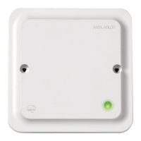
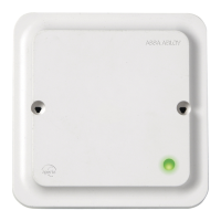
Configuration options for LED behavior based on jumper placement.

Time Delay Settings

Selection of time delay durations for relay activation using jumpers.

Installation Procedure

Prepare Door Jamb

Steps to prepare the door jamb, including marking, drilling, and conduit hole creation.

Install Conduit Housing

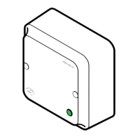
Attaching the conduit housing to the door jamb using mounting screws.

Install Switch Unit

Connecting wiring and attaching the Wave to Open switch to the housing.

Product Operation

Operating Modes and Hand Activation

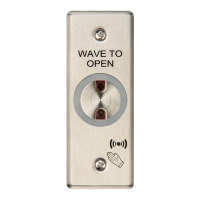
Description of standby/operating modes and how to activate the switch with hand movement.

Relay Activation and Backup Button

Explanation of relay activation timing and the function of the backup button.

Related product manuals