18
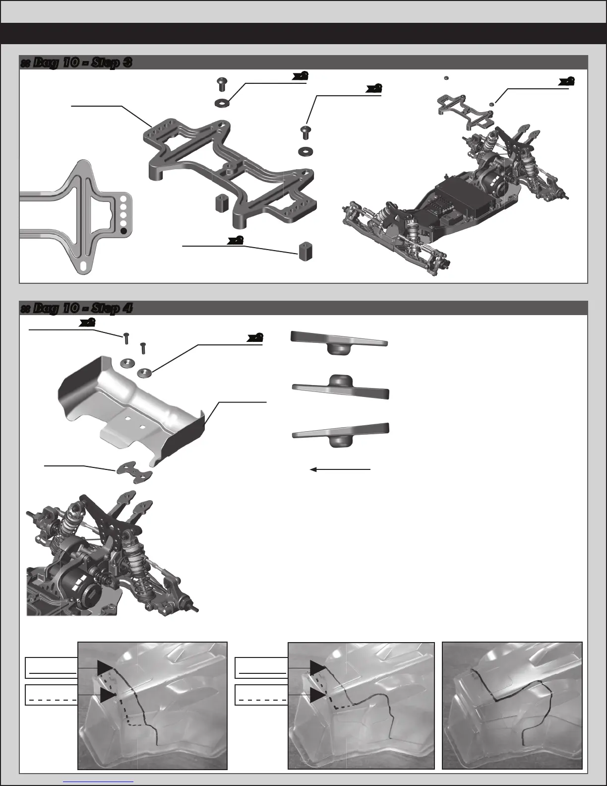
:: Bag 10 - Step 4
Pic 1: Pic 2: Pic 3:
Body Trimming / Mounting:
There are 3 body trimming options depending on what transmission and
shock position you choose to run.
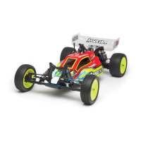
Laydown (Pic 1): Laydown Transmission.
• Cut Line A is for shocks mounted in front of arm.
• Cut line B is for shocks mounted in rear of arm.
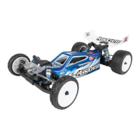
Layback (Pic 2): Layback Transmission.
• Cut Line A is for shocks mounted in front of arm.
• Cut line B is for shocks mounted in rear of arm.
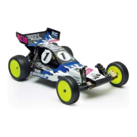
Standup (Pic 3): 3 Gear Stand Up Transmission.
:: Bag 10 - Step 3
Front of Vehicle
0° - Mount under wing
3° - Mount on top of wing
6° - Mount under wing - KIT
91718
Wing
Button
91741
Wing,
B6
91718
Wing
Mount
25202
M3 x 10mm
FHCS
x2
x2
1
2
3
4
5
Front
31531
M3 x 6mm
BHCS
89218
3 x 8mm
Washer
x2
x2
x2
91731
Battery
Strap, B6
91731
Battery
Strap Nut,
B6
91729
Thumb
Screw, B6
x2
Cut Line B
Cut Line A
Cut Line B
Cut Line A
Wing Mount








 To Next Page