0
Fig.
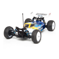
84
Fr
om
Bag
7-4
install and tighten the two
4/40
x
1/4" SHCS
sc
rews in the rear
of
the
chass
is and the
motor
plate,
as shown.
Fig.
84
0
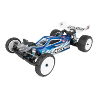
Fig.
85
Lightly
s
nug
all
the screws
in
figs. 79,
80,
81,
82
,
and
83. Now
go
b
ack
and
ti
ghten
all
those screws,
being careful
again not to overtighten the ones
in
plastic.
Fig.
85
page
26
0
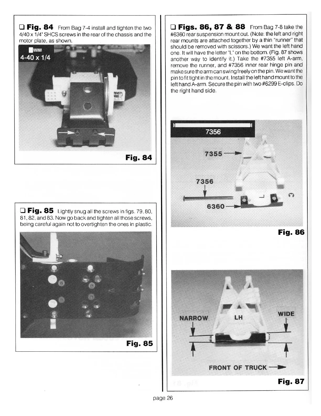
Figs.
86,
87
&
88
From Bag 7-8 take the
#6360 rear suspension mount out. (Note: the
left
and right
rear mounts are attached together
by
a thin
"runner"
that
shou
ld
be
removed with scissors.) We
wa
nt the
left
hand
one. It wi
ll
have t
he
letter "L"
on the bottom. (Fig. 87 shows
another
way
to
id
entify it.) Take the #7355
left
A-arm,
remove the runner, and #7356 inner rear
hinge
pin and
make sure the arm
can
swing
freely
on the pin. We want the
pin to fit
tight
in the mount. Install
the
le
ft
hand
mount to the
left
hand
A-arm.
Secure
the pin with two #6299
E-clips.
Do
the right
hand
side.
h
~
7356
, I
7355
•
...
-
7356
/
'
t
6360
Fig.
86
WIDE
FRONT
OF
TRUCK
•
Fig.
87