0
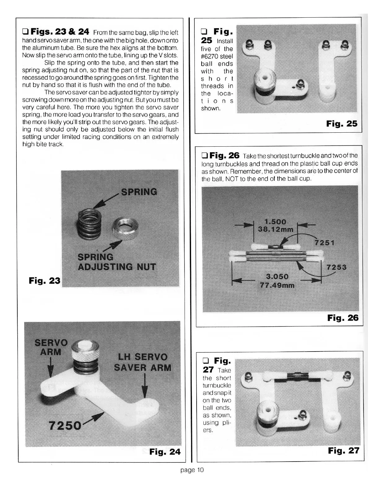
Figs.
23
&
24
From the same bag,
slip
the
left
hand servo saver arm, the one with the
big
hole,
down
onto
the
aluminum
tube. Be sure the hex aligns
at
the bottom.
Now
slip
the servo
arm
onto the tube, lining
up
the
V slots.
Slip
the spring onto the tube, and then start the
spring adjusting nut on,
so
that the part
of
the nut that is
recessed
togo
around the
sp
ring goes on first. Tighten the
nut
by
hand
so
that it is
flush
with the end
of
the tube.
The servo saver
can
be
adjusted tighter
by
simply
screwing
down
more
on
the adjusting nut. But you must
be
very careful
here. The more you tighten the servo
saver
sp
ring, the more
l
oad
you transfer to the servo gears, and
the more likely you'll
strip out the servo gears. The adjust-
ing nut
should only
be
adjusted
below
the initial flush
se
tting
un
der
limited
racing
cond
itions on an
extremely
high bite track.
Fig.
24
0
Fig.
25
Install
five
of
the
#6270
steel
ball
ends
with
the
s
h
o r
t
threads
in
the
loca-
l
i
o n s
shown.
Fig.
25
0
Fig.
26
Take the shortestturnbuckle
and
two
of
the
long turnbuckl
es
and thread on the
plastic ball
cup
ends
as shown. Reme
mber
, the dimensions are to the center of
the ball, NOT
to the end
of
the
ball
c
up
.
D
Fig.
27
Take
the
sho
rt
turnbuckle
and snap it
on the two
ball
ends,
as shown,
using
pli-
ers.
Fig.
26
Fig.
27
page
10