0
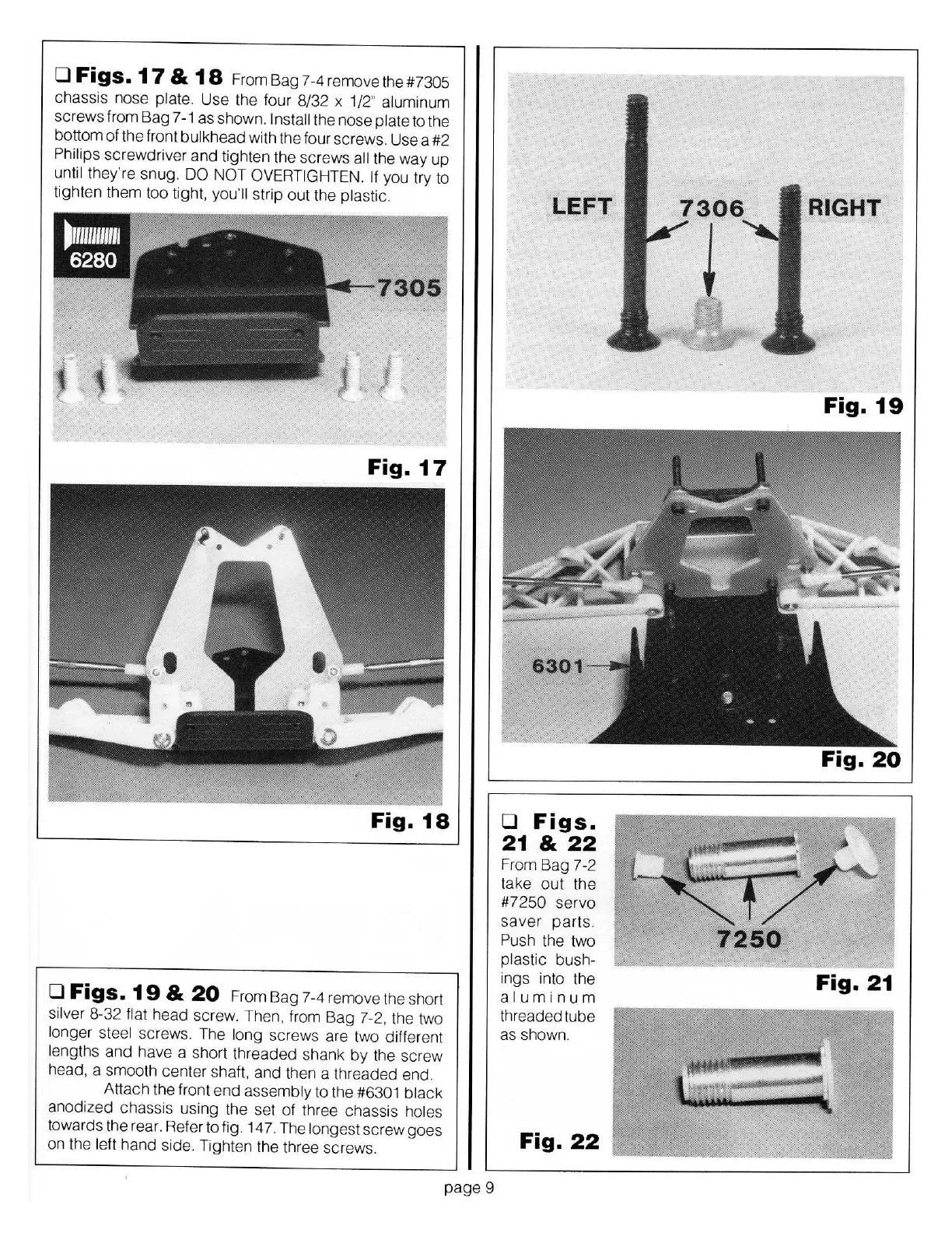
Figs.
17
&
18
From Bag 7-4removethe#7305
chassis nose plate.
Us
e the four 8/32 x
1/2" aluminum
sc
rews from Bag 7
-1
as shown.
Install
the nose
plate
to the
bottom of the front
bulkhead
with the four screws. Use a #2
Ph
ilips
sc
rewdriver
and
tighten the
sc
rews
all
the way up
until
they're snug.
DO NOT OVE
RT
I
GH
TEN. If
you try to
ti
ght
en
th
em t
oo
tight,
you'
ll
strip out the
plastic.
Fig.
18
0
Figs.
19
&
20
From Bag 7-4 remove the short
silver 8-32
flat
h
ead
sc
rew. Then. from Bag 7-2, the two
longer steel
screws. The l
ong
sc
rews are
tw
o different
lengths
and
have a short threa
ded
shank
by
the screw
head, a smooth center shaft. and
th
en a threaded end.
Attach the front
end
assembly
to the
#6301 bl
ack
anodized chassis using the set of three chassis
holes
towards the rear. Refer to fig. 147. The
longest
screw goes
on the
left hand s
id
e. Tighten the three screws.
page9
0
Figs.
21
&
22
From Bag 7-2
take
out
the
#7250
servo
saver
par
ts.
Push
the two
plastic bush-
ings i
nt
o the
aluminum
threaded tube
as shown.
Fig.
22
Fig.
21