0
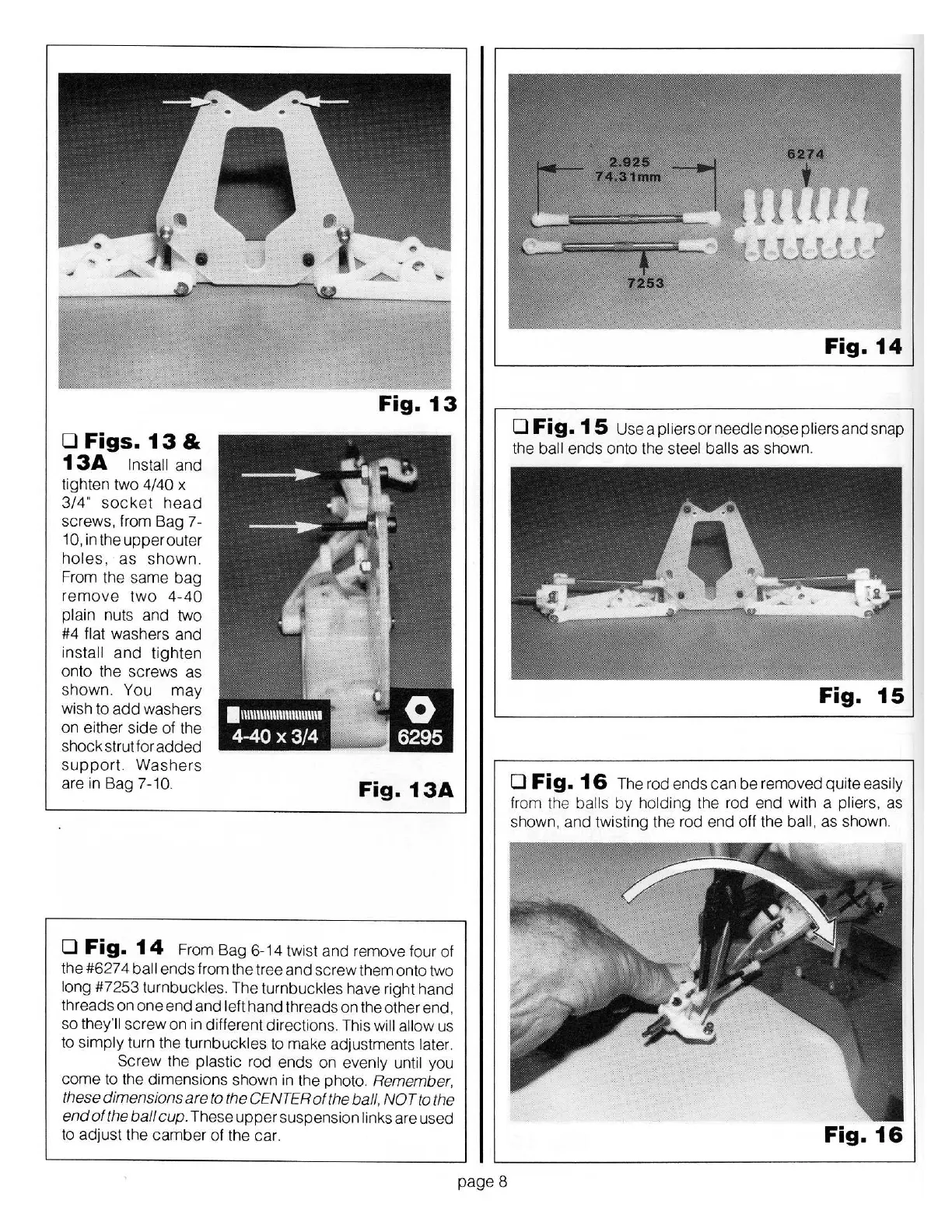
Figs.
13
&
13A
Install and
tighten two 4/40 x
3/4"
socket
head
screws. from Bag 7-
10, in the upper outer
holes,
as
shown.
From the same
bag
remove
two
4-40
plain nuts and two
#4 flat washers and
install
and
tighten
onto the screws as
shown. You
may
wish to
add
washers
on
either side
of
the
shock strut for
added
support.
Washers
are in Bag 7-10.
Fig.
13
Fig.
13A
0
Fig.
14
From Bag 6-14 twist
and
remove four
of
the #627 4 ball ends from the tree and screw them onto two
long #7253 turnbuckles. The turnbuckles have right hand
threads on
one
end
and
left hand threads on the other end,
so they'll
screw
on
in different directions. This will allow us
to simply turn the turnbuckles to make adjustments later.
Screw the plastic rod ends on evenly until you
come
to the dimensions shown in the photo. Remember.
these dimensions are
to
the CENTER
of
the ball, NOT
to
the
end
of
the ball cup. These
upper
suspension links are used
to adjust the camber
of
the car.
page 8
Fig.
14
0
Fig.15
Useapliersorneedleno
_
sepliersandsnap
the ball ends onto the steel balls as shown.
Fig.
15
0
Fig.
16
The rod ends can
be
removed quite easily
from the
ba
lls
by
holding the rod
end
with a pliers. as
shown,
and
twisting the rod end
off
the ball, as shown.
Fig.
16