3
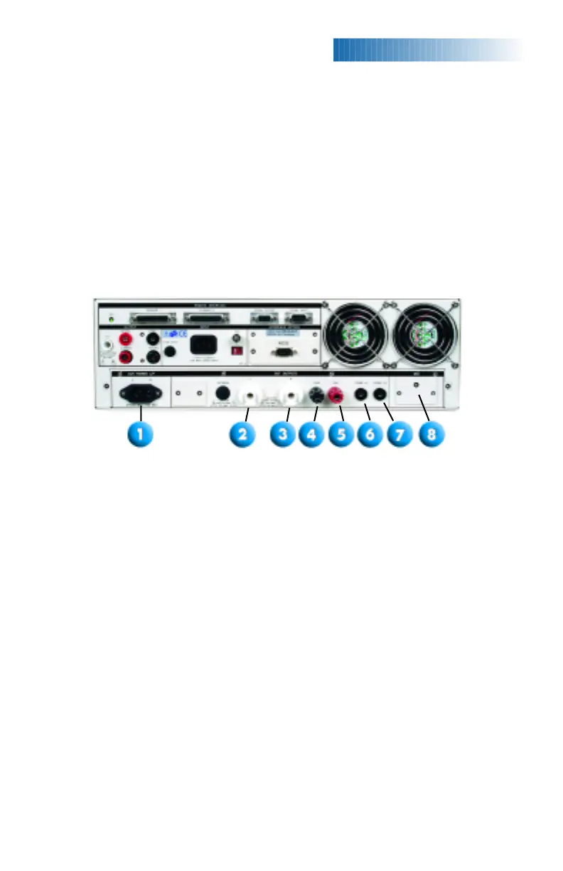
1. DUT POWER INPUT CONNECTOR : Connector provides line and neutral
input power connections. The input is rated for 0 - 277 volts 50/60 hertz.
2. L: Output terminal where the line power connection from the adapter box
is plugged into the run test or line leakage test.
3. N: Output terminal where the neutral power connection from the adapter
box is plugged into the run test or line leakage test.
4. CASE: Terminal connected to the DUT case or dead metal and provides
the return for the Ground Bond, Dielectric Withstand, and Insulation
Resistance tests.
5. GND: Terminal where the ground or earth terminal from the adapter box
is connected.
6. PROBE HI: Terminal input to one side of the measuring device (MD) and
will be enabled during a line leakage test whenever Probe HI has been
selected at setup. This terminal is provided for performing enclosure
leakage or applied part leakage tests.
7. PROBE LO: Terminal input to one side of the measuring device (MD) and
will be enabled during a line leakage test whenever Probe LO has been
selected at setup. This terminal is provided for performing applied part
leakage tests and is always used in conjunction with the Probe HI terminal.
8. EXTERNAL MEASURING DEVIC
E
:
This compar
tment contains an exter
nal
measuring device PCB. When selected, this device will be enabled during
a line leakage test.
13. RETURN OUTPUT TERMINAL : Connector used to attach the return test
lead or test fixture to the instrument. This connector provides the return
current path for the high voltage, ground bond and continuity current.
14. INPUT POWER RECEPTACLE : Standard IEC 320 connector for connection
to a standard NEMA style line power (mains) cord.
15. INPUT POWER SWITCH : In the left position line voltage is set for 115 volt
operation, in the right position line voltage is set for 230 volt operation.
16. SCANNER OUTPUTS : Optional scanner matrix that provides 8
High Voltage/Return connections and 8 Ground Bond connections
(8104 only).
BACK
PANELCONTROLS
8105/8106 BACK PANEL CONTROLS
 Loading...