GENERAL DESCRIPTION OF
SYSTEM
The GMP-025 Meter-Mix-Dispense system has two
gerotor type gear metering pumps (GMP) that are
powered with an electric motor. The system consists of
seven major sections. Each of the components is
described below.
1. Inlet Assembly
2. Electrical Drive Motor & Gear Reducer
3. Gear Metering Pumps and Material Outlets
4. Delivery Hoses
5. Dispense Valve
6. Mixer
7. Controls
This system is designed for use only with the material
specified on the T.E.D. sheet for this system. Use of
other materials is not approved without explicit factory
consent and may cause poor results, damage the
system, or other problems, which is considered misuse
under AST warranty.
Each of the major sections is described below.
If supplied, the air dryer assembly (See BOM & Drawing
#55472A) consists of a desiccant canister connected by
polyurethane tubing to the bent in each tank lid. A small
window on the side of the canister allows the user to view
the contents. When the light blue to any other color, the
canister should be replaced.
NOTE: New canisters need holes punctured in each end
of the canister for the system to work properly. Failure to
do so will result in problems with the dispense ratio.
Each tank contains a screen assembly to prevent any
debris or unwanted particles from entering the pump. This
screen should be removed and cleaned periodically to
prevent blockage inside the tank.
The inlet block connects the tank/inlet assembly to the
gear pump. The block is connected by (4) 5-16”-18 x 2-
1/4” bolts. Removing these 4 bolts will allow the entire
inlet assembly to be removed from the machine.
#60065-02: Page #2
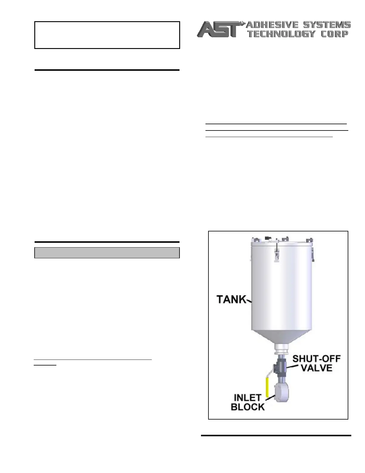
Each inlet assembly consists of a tank, lid, manual shut-
off valve, and a pump inlet block. Typically, 5-gallon
stainless steel tanks with a cone bottom are supplied
with the unit (other options are available). The tanks are
piped to the gear pump inlets. Each tank has three lid
clamps, which may require occasional adjustment to
maintain the lid seal.
Manual shut-off valves are installed between the
material tanks and the gear pumps. These valves can
be shut before servicing the pump to allow most of the
material in the tank to remain inside. The valves should
also be shut during transportation of the unit.
NOTE: Each manual shut-off valve must be open during
dispensing.
Each lid has a silicone gasket that can be scraped out
when it becomes damaged over time. The shape of the
lid allows the gasket to be re-made with any RTV
silicone. Each lid also has a vent to allow air inside the
tank as the material is pumped out. For moisture-
sensitive materials, this vent is connected to an air dryer
assembly
1. INLET ASSEMBLY
 Loading...