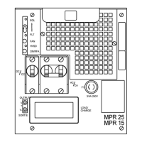
26 Installation and start-up
UM5C06D ( 169-2071-504 ) P0831010 Standard 7.00 May 2001
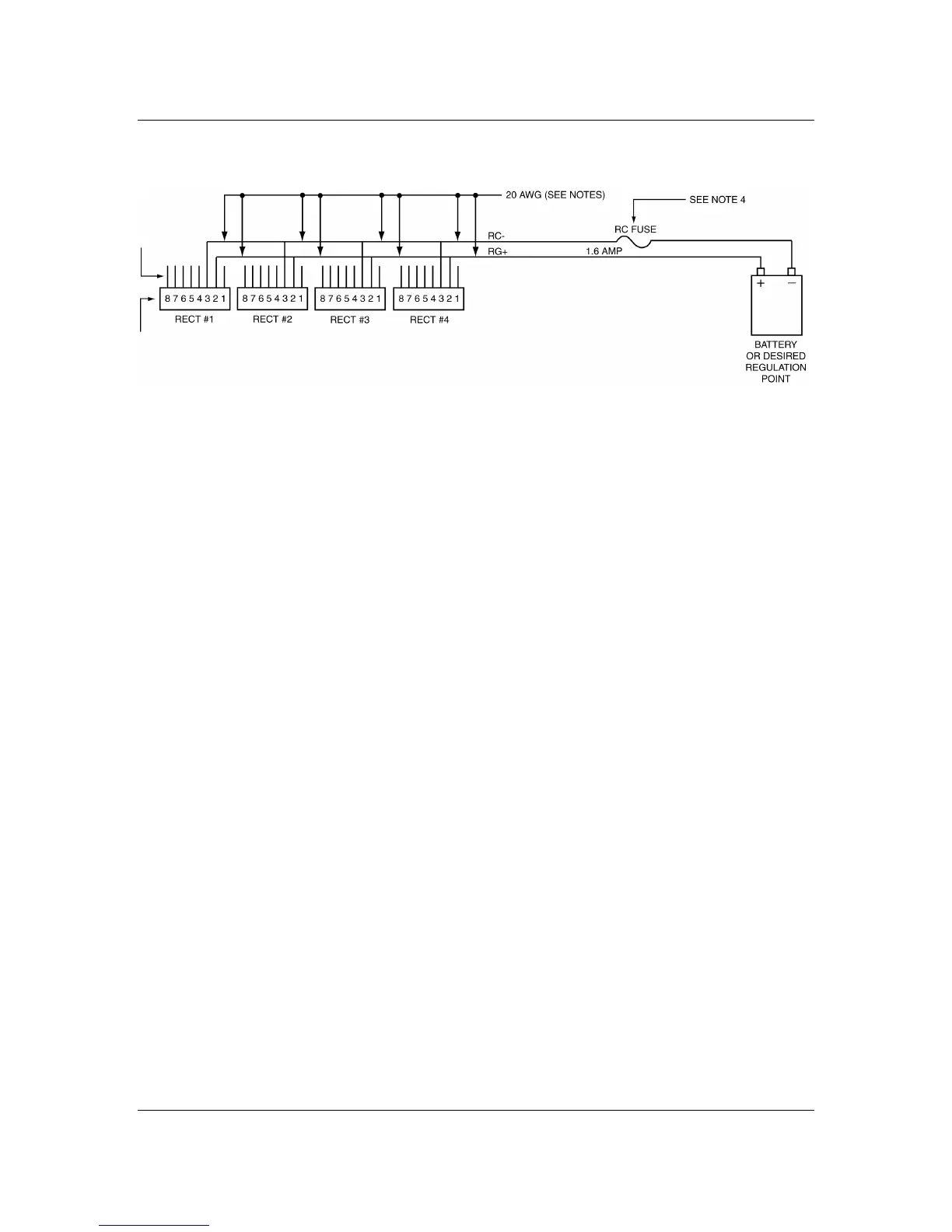
Figure 7 - No controller, remote sensing connection for 8-pin signal cable shelves
Note 1:
Refer to MS5C06 for available 8-pin ribbon signal cables
of different lengths to connect from the shelf back plane
rectifier position to the remote sensing point.
Note 2:
Identify the wire color corresponding to RG+ pin 2 and
RC- pin 3 to be used for the remote sensing. Completely
cut out completely the 8-pin connector, leaving the signal
wires loose. Insulate each unused wire with electrical tape.
Use the pin references to identify the signals as described
above.
Note 3:
Use #20 AWG (105°C) wire.
Note 4:
Use 1.6A fuse A0384386 with ferrule type fuse holder
A0384387.