Operation 39
Helios Rectifier 25/48 Installation and User Manual
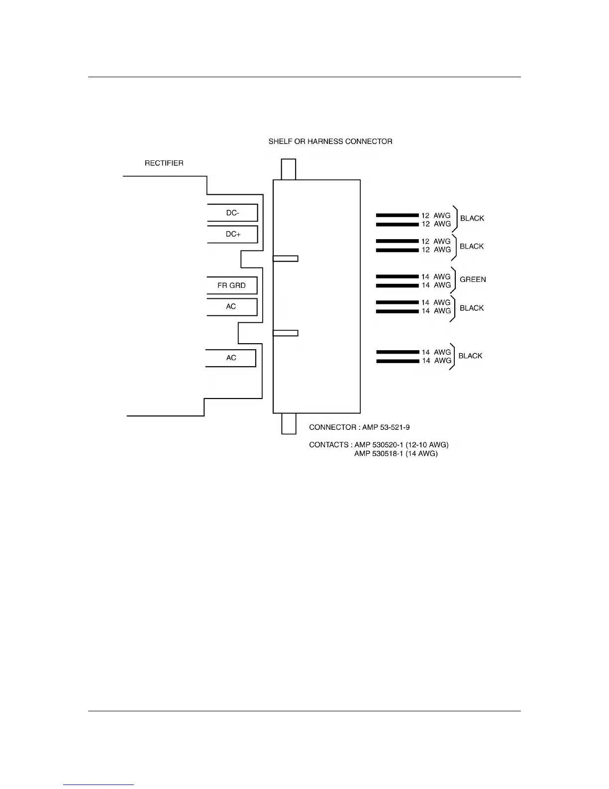
Figure 10 - Power interface connections
Signal interface connector
Figure 11 shows the pin assignment of the signal interface connector. This
connector is used to interface all the control, alarm and monitoring signals
with the power shelf that, in turn, interfaces these with the Controller. The
control inputs are activated by a ground (BAT RTN) signal. The alarms are
extended by relay contacts and are isolated from each other and from the
chassis. All contacts are rated 60 V DC and 0.5 A.