4
3. GENERAL CHARACTERISTICS
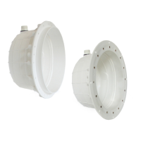
• To complete the spotlight’s installation, one of the faceplates with the following product codes and a Lu-
miPlus FlexiMini fastener must be purchased: 74392, 74393, 74394 or 74395. See corresponding manual.
• It complies with international lighting safety standards, specifically, with standard EN 60598-2-18: LUMI-
NAIRES - PART 2: PARTICULAR REQUIREMENTS. SECTION 18: LUMINAIRES FOR SWIMMING POOLS AND
SIMILAR APPLICATIONS.
• The manufacturer may not be held liable for any damage caused by the mishandling, poor installation or
addition of any electrical components that have not been made by it.
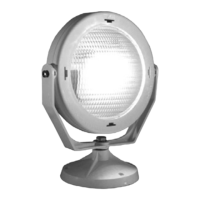
• The spotlight only works if totally submerged in water.
• The light source of this luminaire is not replaceable. When the light source reaches the end of its service
life the whole of the luminaire must be replaced.
• Accessing the inside of the spotlight is totally prohibited. If handled, it will no longer be covered by the
guarantee.
• Water operating temperature: Minimum 5 ºC - Maximum 40 ºC.
• Maximum installation depth: 2 meters (between 0.4 and 0.7 meters is recommended) from the surface of
the water. IPX8 protection rating.
4.ELECTRICAL WIRING (See pages 69–70)
• The service engineer is responsible for ensuring that the area around the connectors protected by the
cable gland is watertight.
• The safety transformer’s capacity must be calculated on the basis that the total load connected must be
over-scaled by 30%.
• We recommend using AstralPool’s underwater connection kit (code 32803) should it be necessary to ex-
tend the cable included (max. 2 x 6 mm² H07RN8-F).
• Should the cable included with the spotlight not be used, the following considerations must be taken into
account:
- The minimum cable cross-section that can be threaded through the cable gland is 2 x 1 mm² H07RN8-F
and the maximum is 2 x 1.5 mm² H07RN8-F.
- It is the service engineer’s responsibility to calculate the cable cross-section required, based on the total
load, cable length and maximum voltage drop allowed by the laws in force, in order to ensure that the
spotlight is fed by 12 V AC.
See the cable cross-section tables according to the spotlight, type of installation and cable length.
• The projector’s power supply does not have polarity.