measured.
4) Read LCD display. The polarity of the RED lead
connection will be indicated when making a DC
measurement.
Note:
a. In small range example mV range , the meter
may display an unstable reading when the test
leads have not been connected to the load to be
measured. It is normal and will not affect the
measurements.
b. To avoid damage to the meter, don’t measure a
voltage which exceeds 600V (for DC voltage
measurement) or 600V(for AC voltage
measurement) , under CAT III conditions.and
1000V(for DC voltage) 750V(for AC voltage)
under CAT II conditions.
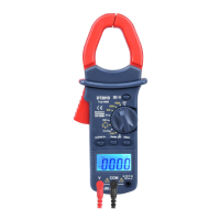
6-2. Measuring Current
1) Set Function/Range Switch to the 60A 600A 1000A
range.
2) Press the trigger to open the transformer jaws and
clamp one conductor only it is impossible to make
measurements when two or three conductors are
clamped at the same time.
3) Display reading is flowing the conductor AC current.
6-3. Measure Resistance
1) Connect the BLACK test lead to the “COM” jack and
the RED to the“ ”jack (Note: The polarity
of the red test lead is positive “+”).
2) Set the function switch to range.
 Loading...