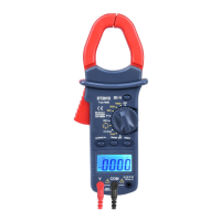
6-5. Diode Test
1) Connect the BLACK test lead to the “COM” jack and
the RED to the“ ” jack (Note: The polarity
of the red test lead is positive “+”).
2) Set the function switch to“ range
3) Press the “SELECT” Button to select continuity
measurement mode, and the symbol “ ” will appear
as an indicator.
4) Connect the red test lead to the anode of the diode to
be tested and the black test lead to the cathode.
5) The meter will show the approximate forward voltage
of the diode. If the connections are reversed, “OL” will
be shown on the display.
6-6. Measuring Temperature
1) Set the function range switch at the TEMP position.
2) Make sure the polarity of the thermocouple is correct;
put the cold end (free end) of the thermocouple sensor
into the terminal (black to COM jack and red to
“ ” jack).
3) Set the working end (testing end) on or inside the
object under test.
4) The value of the temperature is shown on the display
in degree centigrade (°C).
5) Press the “SELECT” Button,fahrenheit and celsiuscan
be converted to each other.
6-7. Capacitance Measuring
1) Connect the BLACK test lead to the “COM” jack and the
 Loading...