14
ASUS A7V User’s Manual
3. HARDWARE SETUP
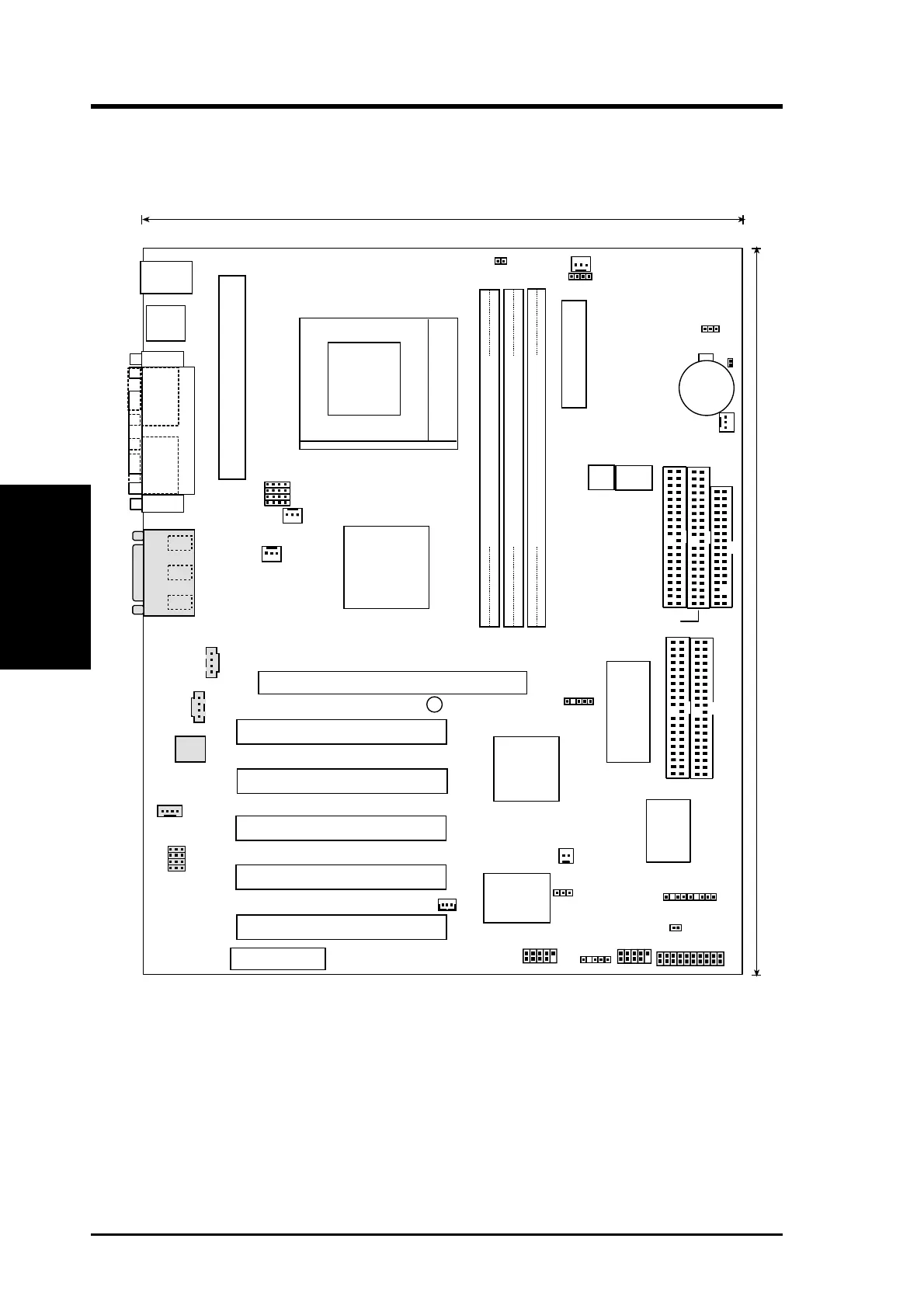
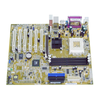
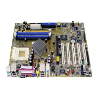
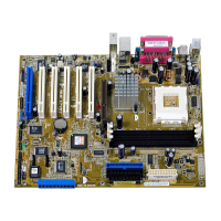
3.1 Motherboard Layout
24.5cm (9.64in)
30.6cm (12in)
CPU_FAN
01
DIMM3 (64/72 bit, 168-pin module)
5 4
PWR_FAN
WOR
CD
MODEM
AUX
Accelerated Graphic Port (AGP PRO)
PCI Slot 1
PCI Slot 3
PCI Slot 2
PANEL
FLOPPY
SECONDARY IDE
ATX Power Connector
VIA
VT82C686A
01
DIMM2 (64/72 bit, 168-pin module)
3 2
01
DIMM1 (64/72 bit, 168-pin module)
1 0
Row
USB3
Audio Modem Riser
(AMR)
A7V
Audio
Codec
SMB
2Mbit Flash EEPROM
(Programmable BIOS)
CHA_FAN
DSW
DIP Switches
3VSBSLT
PRIMARY IDE
IDELED
CLRTC
PS/2
T: Mouse
B: Keyboard
USB
T: Port0
B: Port1
JEN
JTPWR
CHASSIS
PCI Slot 5
PCI Slot 4
COM1
COM2
PARALLEL PORT
GAME_AUDIO
Mic
In
Line
Out
Line
In
VIA
VT8363
AGP4X &
PC133 Memory
Controller
CR2032 3V
Lithium Cell
CMOS Power
ASUS
ASIC
AS99127
USB3A
WOLCON
USBPORT
ATA100
IDE
Controller
PLED
VIO
IR
AUD_EN1
AUD_EN2
ADN#
SPK
VID1
VID2
VID3
VID4
Socket 462
PRIMARY Ultra ATA100 IDE
SECONDARY Ultra ATA100 IDE
F_FAN
SK7VRM
DSFID
Motherboard Layout
3. H/W SETUP
Grayed components are optional at the time of purchase (JTCPU is no longer neces-
sary on motherboards with PCB versions 1.02 and later)