1-8
Chapter 1: Product introduction
Chapter 1
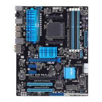
Layout contents
Connectors/Jumpers/Slots Page
1. ATX power connectors (24-pin EATXPWR, 8-pin EATX12V) 1-40
2. AM3+/AM3 CPU Socket 1-9
3. CPU and chassis fan connectors (4-pin CPU_FAN; CHA_FAN1/2/3) 1-38
4. DDR3 DIMM slots 1-10
5. EPU LED (O2LED3) 1-33
6. EPU Switch 1-28
7. MemOK! button 1-27
8. POST State LEDs 1-31
9. DirectKey button 1-26
10. USB 3.0 connector (20-1 pin USB3_34) 1-35
11. AMD
®
Serial ATA 6.0 Gb/s connectors (7-pin SATA6G_1-6 [gray]) 1-34
12. TPU Switch 1-29
13 TPU LED (O2LED2) 1-32
14. Clear RTC RAM (3-pin CLRTC) 1-30
15. Direct connector (2-pin DRCT) 1-42
16 System panel connector (20-8 pin PANEL) 1-41
17. Serial port connector (10-1 pin COM1) 1-39
18. USB 2.0 connectors (10-1 pin USB910, USB1112, USB1314) 1-36
19. Standby Power LED 1-31
20. TPM connector (20-1 pin TPM) 1-42
21. BIOS Flashback LED (FLBK_LED) 1-32
22. USB BIOS Flashback button 1-28
23. IEEE 1394a port connector (10-1 pin IE1394_2) 1-37
24. Front panel audio connector (10-1 pin AAFP) 1-39
25. Digital audio connector (4-1 pin SPDIF_OUT) 1-37
26. POST State LEDs 1-31
 Loading...