ASUS P5AD2-E PremiumASUS P5AD2-E Premium
ASUS P5AD2-E PremiumASUS P5AD2-E Premium
ASUS P5AD2-E Premium
2-332-33
2-332-33
2-33
14.14.
14.14.
14.
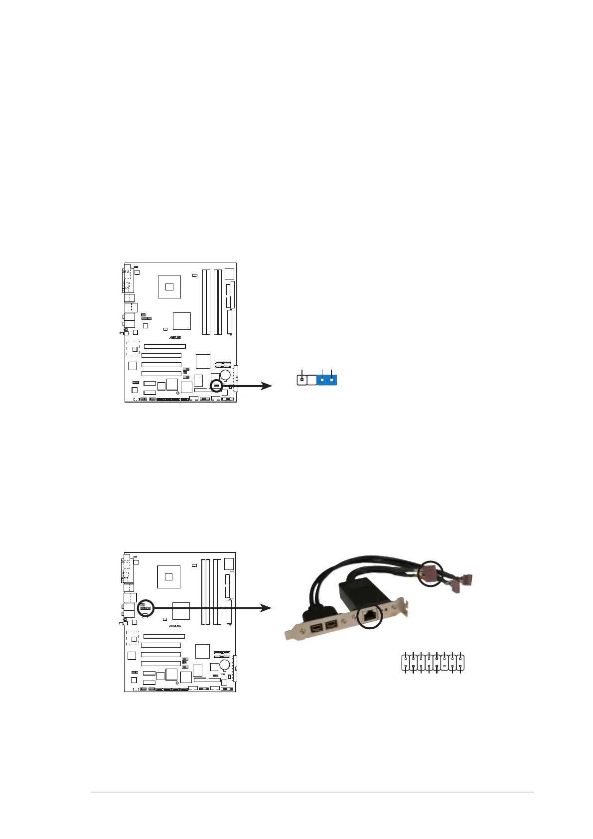
Chassis intrusion connector (4-1 pin CHASSIS1)Chassis intrusion connector (4-1 pin CHASSIS1)
Chassis intrusion connector (4-1 pin CHASSIS1)Chassis intrusion connector (4-1 pin CHASSIS1)
Chassis intrusion connector (4-1 pin CHASSIS1)
This connector is for a chassis-mounted intrusion detection sensor or
switch. Connect one end of the chassis intrusion sensor or switch
cable to this connector. The chassis intrusion sensor or switch sends a
high-level signal to this connector when a chassis component is
removed or replaced. The signal is then generated as a chassis
intrusion event.
By default, the pins labeled “Chassis Signal” and “Ground” are shorted
with a jumper cap. Remove the jumper caps only when you intend to
use the chassis intrusion detection feature.
15.15.
15.15.
15.
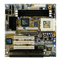
Gigabit LAN port connector (16-1 pin LAN2 [black])Gigabit LAN port connector (16-1 pin LAN2 [black])
Gigabit LAN port connector (16-1 pin LAN2 [black])Gigabit LAN port connector (16-1 pin LAN2 [black])
Gigabit LAN port connector (16-1 pin LAN2 [black])
This connector is for a Gigabit LAN (RJ-45) port. Connect the LAN
(RJ-45) port module cable to this connector, then install the module
to an opening at the back of the system chassis. The Gigabit LAN
(RJ-45) port allows up to 1 Gbps LAN or Internet connection.
P5AD2-E
PREMIUM
®
P5AD2-E PREMIUM Chassis intrusion connector
CHASSIS1
+5VSB_MB
Chassis Signal
GND
(Default)
P5AD2-E
PREMIUM
®
P5AD2-E PREMIUM Gigabit LAN port connector
LINK_100# LINK_GB#
Act# LED_Power
CTR
GND
GND
TD1+ TD1-
TD2+ TD2-
TD3+ TD3-
TD4+ TD4-
LAN2