1-22 Chapter 1: Product introduction
2. IDE connector (40-1 pin PRI_IDE)
The onboard IDE connector is for the Ultra DMA 100/66/33 signal cable. There are
three connectors on each Ultra DMA 100/66/33 signal cable: blue, black, and gray.
Connect the blue connector to the motherboard’s IDE connector, then select one of the
following modes to congure your device.
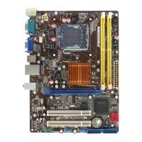
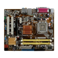
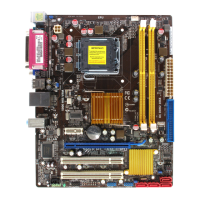
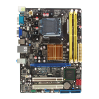
P5KPL-AM SE
PRI_IDE
NOTE:Orient the red markings
on the IDE ribbon cable to PIN 1.
PIN1
P5KPL-AM SE IDE connector
Driver Jumper setting Mode of device(s) Cable connector
Single device Cable-Selected or Master - Black
Two devices Cable-Select Master Black
Slave Gray
Master Master Black or gray
Slave Slave
• Pin 20 on the IDE connector is removed to match the covered hole on the Ultra DMA
cable connector. This prevents incorrect insertion when you connect the IDE cable.
• Use the 80-conductor IDE cable for Ultra DMA 133/100/66 IDE devices.
If any device jumper is set as
“Cable-Select,” ensure that all other
device jumpers have the same
setting.
3. Optical drive audio connector (4-pin CD)
These connectors allow you to receive stereo audio input from sound sources such as
a CD-ROM, TV tuner, or MPEG card.
 Loading...