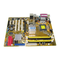
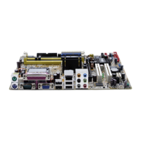
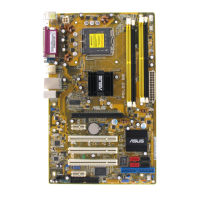
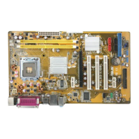
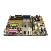
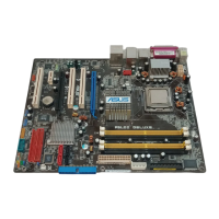
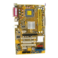
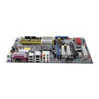
ASUS P5LP-LE (Emery2-UL8E)ASUS P5LP-LE (Emery2-UL8E)
ASUS P5LP-LE (Emery2-UL8E)ASUS P5LP-LE (Emery2-UL8E)
ASUS P5LP-LE (Emery2-UL8E)
1515
1515
15
2.2.
2.2.
2.
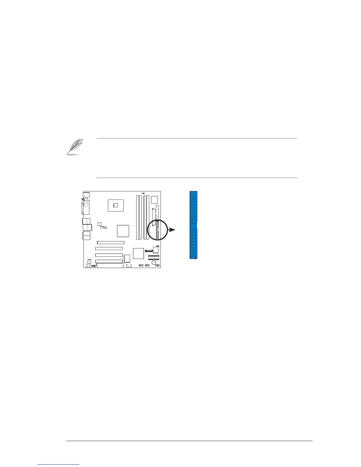
IDE connector (40-1 pin IDE)IDE connector (40-1 pin IDE)
IDE connector (40-1 pin IDE)IDE connector (40-1 pin IDE)
IDE connector (40-1 pin IDE)
This connector is for an Ultra DMA 100/66 signal cable. The Ultra DMA
100/66 signal cable has three connectors: a blue connector for the primary
IDE connector on the motherboard, a black connector for an Ultra DMA
100/66 IDE slave device (optical drive/hard disk drive), and a gray
connector for an Ultra DMA 100/66 IDE master device (hard disk drive).
If you install two hard disk drives, you must configure the second drive as
a slave device by setting its jumper accordingly. Refer to the hard disk
documentation for the jumper settings.
P5LP-LE
P5LP-LE (Emery2-UL8E)
IDE connector
(usually zigzag) on the IDE
ribbon cable to PIN 1.
IDE
PIN 1
• Pin 20 on the IDE connector is removed to match the covered hole on
the Ultra DMA cable connector. This prevents incorrect insertion when
you connect the IDE cable.
• Use the 40-conductor IDE cable for Ultra DMA IDE devices.
 Loading...