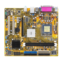
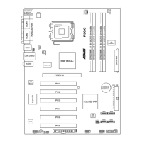
ASUS P5RD1-VMASUS P5RD1-VM
ASUS P5RD1-VMASUS P5RD1-VM
ASUS P5RD1-VM
1-311-31
1-311-31
1-31
7.7.
7.7.
7.
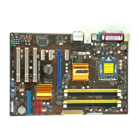
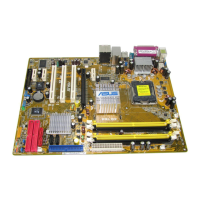
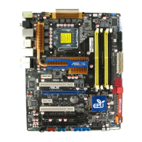
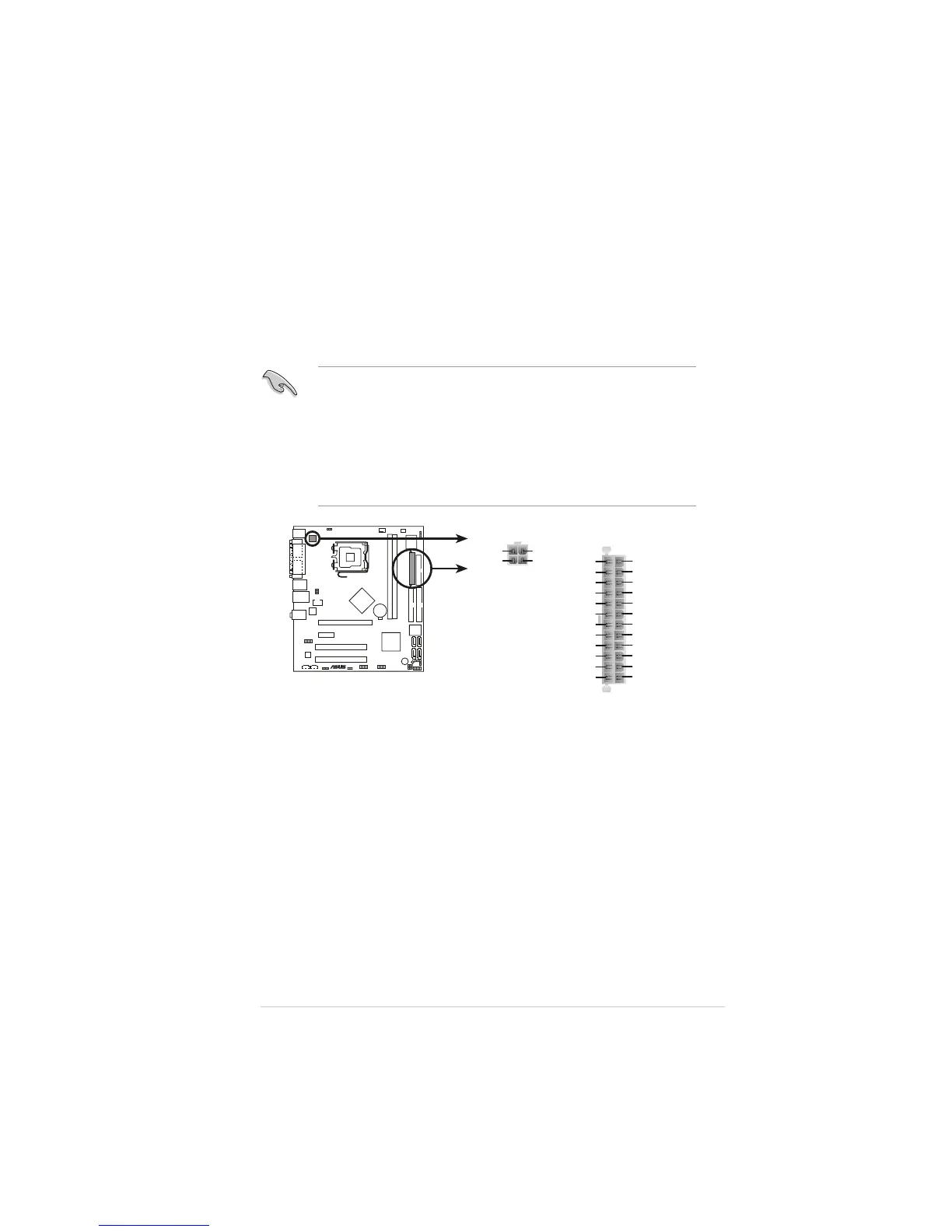
ATX power connectorsATX power connectors
ATX power connectorsATX power connectors
ATX power connectors
(24-pin EATXPWR(24-pin EATXPWR
(24-pin EATXPWR(24-pin EATXPWR
(24-pin EATXPWR
and and
and and
and
4-pin ATX12V)4-pin ATX12V)
4-pin ATX12V)4-pin ATX12V)
4-pin ATX12V)
These connectors are for ATX power supply plugs. The power supply
plugs are designed to fit these connectors in only one orientation.
Find the proper orientation and push down firmly until the connectors
completely fit.
•
Do not forget to connect the 4-pin ATX +12 V power plug;
otherwise, the system will not boot.
• Use of a PSU with a higher power output is recommended when
configuring a system with more power-consuming devices. The
system may become unstable or may not boot up if the power is
inadequate.
• Make sure that your power supply unit (PSU) can provide at least
the minimum power required by your system.
®
P5RD1-VM
P5RD1-VM ATX power connectors
EATXPWRATX12V
+3 Volts
+3 Volts
Ground
+5 Volts
+5 Volts
Ground
Ground
Power OK
+5V Standby
+12 Volts
-5 Volts
+5 Volts
+3 Volts
-12 Volts
Ground
Ground
Ground
PSON#
Ground
+5 Volts
+12 Volts
+3 Volts
+5 Volts
Ground
+12V DC
GND
+12V DC
GND
 Loading...