Do you have a question about the Asus P5SD1-FM2 and is the answer not in the manual?
Precautions to avoid electrical hazards and ensure safe system operation.
Guidelines for safe handling and use of computer components and the system.
Important safety precautions to follow before installing or changing motherboard components.
Study chassis configuration and motherboard placement for proper installation.
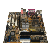
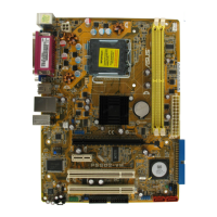
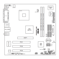
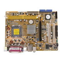
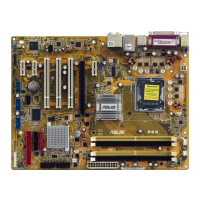
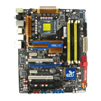
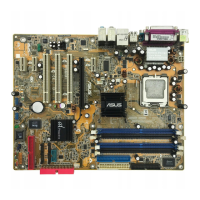
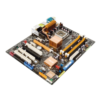
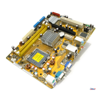
Diagram illustrating the physical arrangement of components and connectors on the motherboard.
Lists and pages for slots, jumpers, and rear panel connectors detailed in the manual.
Step-by-step instructions for safely installing the CPU into its socket on the motherboard.
Guide on how to properly mount and connect the CPU heatsink and fan assembly for cooling.
Procedures for safely removing the CPU heatsink and fan assembly from the motherboard.
Identifies the physical location and type of DDR DIMM sockets on the motherboard.
Details compatible memory module sizes and configuration guidelines for optimal performance.
Step-by-step guide on how to correctly insert a DDR DIMM module into the motherboard socket.
Instructions on how to safely detach and remove a DIMM module from its socket.
Procedures for installing various expansion cards into the motherboard's expansion slots.
Steps to configure installed expansion cards, including BIOS settings and driver installation.
Details standard interrupt assignments and specific IRQ assignments for motherboard devices and slots.
Describes the three PCI slots and the types of cards they support, with an example illustration.
Explains the PCI Express x16 slot for graphics cards, with an example illustration.
Instructions for clearing the CMOS Real Time Clock RAM to reset BIOS settings to default.
Configuration of USB jumpers for wake-up functionality from different sleep modes.
Jumper setting to enable or disable keyboard wake-up feature, requiring specific ATX power supply.
Jumper to enable or skip BIOS password setting, with default and alternative configurations.
Procedure to force BIOS recovery using a jumper and floppy disk if BIOS becomes corrupted.
Details each rear panel port, its function, and color coding for connectivity.
Describes internal motherboard connectors for FDD, power LEDs, IDE, SATA, fans, and system panel.
Explains the primary and secondary IDE connectors for Ultra DMA 100/66 signal cables.
Details Serial ATA connectors for hard disk drives, including RAID features and Master/Slave settings.
Connectors for CPU and chassis fans, specifying power requirements and proper wiring.
Connector for the case-mounted speaker used for system beeps and warnings.
Describes the 10-pin USB connectors for USB 2.0 ports, warning against connecting 1394 cables.
Details the 24-pin and 4-pin ATX power connectors, recommending PSU specifications for stability.
Connector for stereo audio input from sources like CD-ROM, TV tuner, or MPEG card.
Connector for chassis-mounted front panel audio I/O modules supporting AC'97 standard.
Connector for chassis functions like power LED, HDD activity, power button, and reset button.
Steps to create a bootable floppy disk in DOS or Windows XP environments for BIOS updates.
Utility built into BIOS for updating BIOS without booting from a floppy disk during POST.
Utility for updating BIOS in DOS mode and backing up the current BIOS file.
Overview of the BIOS setup utility interface, including menu items, bar, and navigation keys.
Describes the main menu items (Main, Advanced, Power, Boot, Exit) for navigating BIOS settings.
Explains the use of arrow keys and function keys for selecting items and changing settings in BIOS.
Explains how menu items on the bar display specific items for each menu section.
How to change user-configurable values displayed in highlighted fields within BIOS menus.
How to display configuration options for a selected menu item by pressing Enter.
Location and purpose of the brief description for selected items in the BIOS menu.
Allows setting the current system time within the BIOS.
Allows setting the current system date within the BIOS.
Configures the type of floppy disk drive installed for compatibility.
BIOS automatically detects IDE devices, with sub-menus for configuring each device's type and mode.
Enables or disables the onboard PCI Serial ATA controller, with options for Disabled, RAID, or Native.
Displays an overview of general system specifications like BIOS version, processor, and memory detected by the system.
Displays CPU-related information and allows configuration of CPU settings like ratio and microcode.
Allows changing advanced chipset settings for Northbridge and Southbridge components.
Configures onboard devices like serial ports, parallel ports, and IEEE 1394 controllers.
Adjusts advanced settings for PCI/PnP devices, including IRQ and DMA channel resource allocation.
Allows changing USB-related features such as USB function, legacy support, and controller mode.
Enables or disables ACPI support for the operating system, essential for power management features.
Selects the ACPI state used for system suspend, influencing power consumption during idle periods.
Determines if VGA BIOS POST is invoked when resuming from S3/STR state.
Configures Advanced Power Management settings, including power button functionality and wake-up events.
Displays system temperatures, voltages, and fan speeds, and allows configuration of ASUS Q-Fan feature.
Configures settings like Quick Boot, Full Screen Logo, and error handling during the boot process.
| Form Factor | Micro ATX |
|---|---|
| Memory Type | DDR3 |
| Max Memory | 32GB |
| SATA | 4 x SATA 3Gb/s |
| Memory Slots | 2 |
| Expansion Slots | 1 x PCIe 2.0 x16, 1 x PCIe 2.0 x1, 1 x PCI |
| Audio | Realtek ALC887 8-Channel High Definition Audio CODEC |
| LAN | Realtek RTL8111GR Gigabit LAN Controller |
| Power Connector | 24-pin |
| Video Outputs | 1 x D-Sub 1 x DVI-D |
| USB Ports | 8 x USB 2.0 (4 at back panel, 4 at mid-board) |