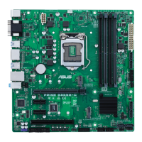
ASUS PRIME B350M-E
1-5
12. Serial port connector (10-1 pin COM)
Thisconnectorisforaserial(COM)port.Connecttheserialport
modulecabletothisconnector,theninstallthemoduletoaslot
opening at the back of the system chassis.
PIN 1
COM
DCD
TXD
GND
RTS
RI
RXD
DTR
DSR
CTS
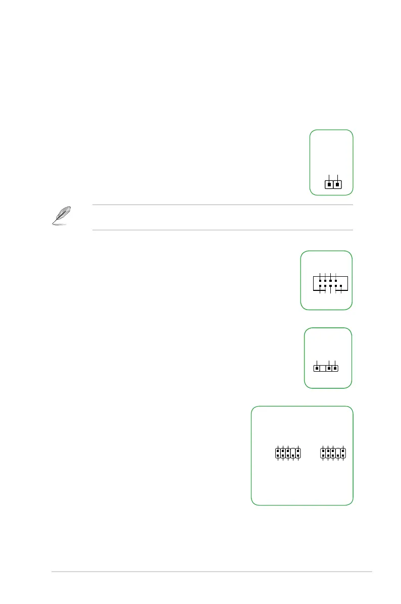
To erase the RTC RAM:
1. TurnOFFthecomputerandunplugthepowercord.
2. Useametalobjectsuchasascrewdrivertoshortthetwopins.
3. PlugthepowercordandturnONthecomputer.
4. Holddownthe<Del>keyduringthebootprocessandenterBIOS
setup to re-enter data.
Ifthestepsabovedonothelp,removetheonboardbatteryandshortthetwopinsagainto
cleartheCMOSRTCRAMdata.AfterclearingtheCMOS,reinstallthebattery.
CLRTC
+3V_BAT
GND
11. Clear RTC RAM (2-pin CLRTC)
ThisheaderallowsyoutocleartheRealTimeClock(RTC)RAMinCMOS.Youcan
cleartheCMOSmemoryofdate,andsystemsetupparametersbyerasingtheCMOS
RTCRAMdata.TheonboardbuttoncellbatterypowerstheRAMdatainCMOS,which
include system setup information such as system passwords.
13. Digital audio connector (4-1 pin SPDIF_OUT)
ThisconnectorisforanadditionalSony/PhilipsDigitalInterface(S/
PDIF)port.ConnecttheS/PDIFOutmodulecabletothisconnector,
then install the module to a slot opening at the back of the system
chassis.
SPDIF_OUT
+5V
SPDIFOUT
GND
14. Front panel audio connector (10-1 pin AAFP)
This connector is for a chassis-mounted front panel
audioI/OmodulethatsupportseitherHDAudioor
legacyAC`97audiostandard.Connectoneendofthe
frontpanelaudioI/Omodulecabletothisconnector.
AAFP
AGND
NC
SENSE1_RETUR
SENSE2_RETUR
PORT1 L
PORT1 R
PORT2 R
SENSE_SEND
PORT2 L
HD-audio-compliant
pin definition
PIN 1
AGND
NC
NC
NC
MIC2
MICPWR
Line out_R
NC
Line out_L
Legacy AC’97
compliant definition
 Loading...