21
ø22mm
75mm min.
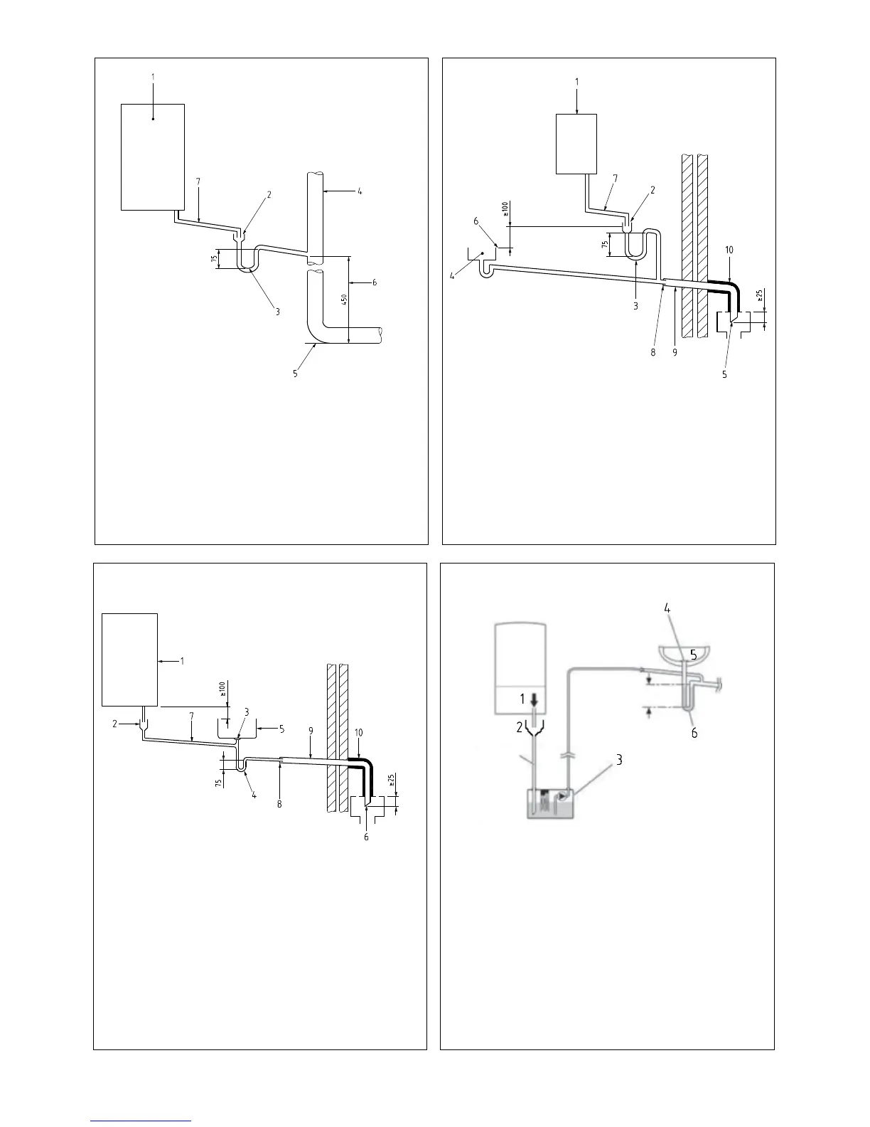
Drain requirements Figure 9.7.2 (b)
1 Boiler
2 Visible air break
3 75mm trap
4 Soil and vent stack
5 Invert
6 450mm minimum up to three storeys
7 Minimum internal diameter 19mm (fall at least 45mm per meter)
1 Boiler
2 Visible air break
3 75mm trap
4 Sink, basin, bath or shower
5 Open end of condensate drainage pipe direct into gully 25mm
min below grating but above water level; end cut at 45°
6 Sink lip
7 Minimum internal diameter 19mm (fall at least 45mm per meter)
8 Pipe size transition
9 Minimum internal diameter 30mm
10 Water/weather proof insulation
Drain requirements Figure 9.7.1 Drain requirements Figure 9.7.2 (a)
Drain requirements Figure 9.7.3
1 Boiler
2 Visible air break
3 Visible air break at plug-hole
4 75 mm sink, basin, bath or shower waste trap
5 Sink, basin, bath or shower with integral overow
6 Open end of condensate drainage pipe direct into gully 25mm
min below grating but above water level; end cut at 45°
7 Minimum internal diameter 19mm (fall at least 45mm per meter)
8 Pipe size transition
9 Minimum internal diameter 30mm
10 Water/weather proof insulation
1 Condensate discharge from boiler
2 Visible air break
3 Condensate pump
4 Visible air break at plug hole
5 Sink or basin with integrated overow
6 75mm sink waste trap

 Loading...


