Do you have a question about the AT&T Digital Life DLC-200C and is the answer not in the manual?
| Model | DLC-200C |
|---|---|
| Category | Controller |
| Manufacturer | AT&T |
| Compatibility | AT&T Digital Life System |
| Dimensions | Unknown |
| Weight | Unknown |
| Device Type | Wireless Controller |
Overview of the AT&T Digital Life System (DLS) and its components.
Describes the IP-based end-to-end services delivery platform of the DLS.
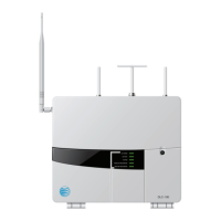
Details the second-generation Digital Life Controller (DLC) and its cabinet.
Explains the LED indicators during the DLC-200C firmware upgrade process.
Describes the LED behavior when the security certificate expires.
Explains the LED behavior during the power-on test.
Lists the standard modules included in the DLC-200C cabinet.
Illustrates the battery compartment door with a captured screw and tamper switch.
Shows the mounting plate captured screw with tamper switch.
Depicts the Digital Life Premises Devices that communicate with the DLC-200C.
Details the dual frequency wireless transceiver module supporting 433MHz and 915MHz.
Describes the optional conversion kit for existing wired security systems.
Explains the use of Z-Wave 908MHz technology for home automation.
Outlines the system installation and configuration process using a web tool.
Details system operation using keypads and keychain remotes.
Illustrates the 915 MHz two-way wireless keypad and its functions.
Shows the 433 MHz one-way keychain remote and its functions.
Illustrates the 915 MHz two-way keychain remote and its functions.
Explains how the DLC-200C reports alarm messages to the monitoring center.
Describes automatic notifications for specified events within the Digital Life Service.
Details the option for customers to purchase and use indoor/outdoor cameras.
Covers purchasing home automation and control devices using Z-Wave technology.
Explains system operation during local power failures, including battery backup.
Describes accessing the DLD Web Tool and logging in to manage the DLC-200C.
Details placing the DLC-200C into Discovery mode and registering devices.
Explains how to place the DLC-200C into Test Mode for system testing.
Details administration of DLC-200C features via the DLD "Devices" tab.
Shows the DLD interface for Alarm Manager information and configuration.
Lists administrative features of the Alarm Manager.
Lists the various Alarm Manager (AM) Flags available for configuration.
Explains resetting Exit Delay when arming Away or Stay.
Describes the keypad beep when an alarm is aborted.
Details keypad chirps for door open/close events.
Explains the feature to reduce false smoke alarms by requiring two signals.
Describes automatic arming to STAY mode if user doesn't leave after AWAY arming.
Describes keypad beeps when an alarm is canceled.
Details keypad chirps for specific door open/close events.
Explains enabling the Swinger Shutdown feature.
Details using DLD to troubleshoot wireless devices and monitor signal strength.
Explains how to monitor wireless signal strength for devices.
Shows the alert message when signal strength monitoring starts.
Shows signal strength monitoring with notation for repeated signals.
Shows the base unit of the DLC-200C.
Shows the wall mounting plate for the DLC-200C.
Describes the 433 MHz transceiver module for one-way communication.
Describes the 915 MHz transceiver module for two-way communication.
Illustrates the initial steps for installing the DLC-200C cabinet.
Continues the illustration of DLC-200C cabinet installation steps.
Details the installation process using HomePlug AV (HPAV) technology.
Lists the available HPAV installation kits.
Explains the features and operation of the IP522CG HPAV to Ethernet bridge.
Details the features and operation of the IP532CG unit for IP Cameras.
Details the UL required Exit Time feature and its settings.
Explains UL required progress annunciation during exit time.
Details the UL required Exit Time Restart feature.
Describes the UL required Auto Stay Arm on Unvacated Premises feature.
Details the UL required Entry Delay feature and its settings.
Explains the UL required Abort Window for non-fire zones.
Details the UL required Abort Window Time for non-fire zones.
Describes the UL required Abort Annunciation feature.
Details the UL required Cancel Window feature.
Explains the UL required Cancel Annunciation feature.
Describes the UL required Cross Zoning feature.
Details the UL required Programmable Cross Zoning Time.
Explains the UL required Swinger Shutdown feature.
Details the UL required Swinger Shutdown Disable feature.
Describes the UL required Fire Alarm Verification feature.
Explains how to set and use the Security PIN to disarm the system.
Details how to configure the Entry Delay time for user convenience.
Explains how to configure the Exit Delay time for user convenience.
Describes how to configure the Abort Delay to reduce false alarms.
Details how to set the duration the alarm siren sounds.
Explains the delay required for two intrusion sensors to trip before an alarm.
Details the false alarm prevention feature that auto-bypasses devices.
Lists the various Alarm Manager (AM) Flags available for configuration.
Explains resetting Exit Delay when arming Away or Stay.
Describes the keypad beep when an alarm is aborted.
Details keypad chirps for door open/close events.
Explains enabling the Swinger Shutdown feature.
Details using DLD to troubleshoot wireless devices and monitor signal strength.
Explains how to monitor wireless signal strength for devices.
Shows the alert message when signal strength monitoring starts.
Shows signal strength monitoring with notation for repeated signals.
Shows the base unit of the DLC-200C.
Shows the wall mounting plate for the DLC-200C.
Describes the 433 MHz transceiver module for one-way communication.
Describes the 915 MHz transceiver module for two-way communication.
Illustrates the initial steps for installing the DLC-200C cabinet.
Continues the illustration of DLC-200C cabinet installation steps.
Details the installation process using HomePlug AV (HPAV) technology.
Lists the available HPAV installation kits.
Explains the features and operation of the IP522CG HPAV to Ethernet bridge.
Details the features and operation of the IP532CG unit for IP Cameras.
Important safety instructions for qualified service personnel.
Reminders for system installers regarding coaxial cable grounding.
Essential safety precautions for operating and servicing the apparatus.
Warning about using the correct power source and avoiding overloads.
Instructions on proper grounding to prevent electrical hazards.
Guidance on checking the power source via the indicator light.
Warning against overloading AC power sources.
Instructions for ventilation and location selection for proper operation.
Warnings against exposing the product to liquids or foreign objects.
Warnings about opening the product, voiding the warranty, and no user-serviceable parts.
Mandates safety checks after any service or repair.
Advises disconnecting power before moving the apparatus.
Warnings about battery hazards if mishandled, requiring specific replacements.