7
Version 1.0 11/2018
User Manual—Streaming Device and Remote Control
B. Client Hardware
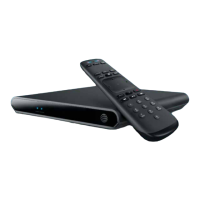
1. Front Panel
• Blue Power Status Indicator LED • Green / Yellow / Red Network Status Indicator
FIGURE 1: STREAMING DEVICE—FRONT PANEL
2. Side Panel
• Red Reset Button
FIGURE 2: STREAMING DEVICE—SIDE PANEL
3. Rear Panel
• 10/100 Ethernet Connector with Indicator LED
• S/PDIF Optical Audio Connector
• HDMI Connector (Type A)
• USB 2.0 Port (Type A Connector)
• DC Power Inlet Connector
(for EPS10 External Power Supply)
with Power Indicator LED
FIGURE 3: STREAMING DEVICE—REAR PANEL
 Loading...