•
f\
3.07
Insert
the plug end of the D5AL or D5AN
mounting cord (Fig.
7)
into the jack located
on
the
underside
of
the
base
assembly.
Make
sure
that
the
spring
clip
of
the
plug
snaps
into
place
to
secure
the
plug.
Lay the cord
in
the
cord channel and slide the cord retainer over the
cord .
Fig.
7-DSAL
Mounting
Cord
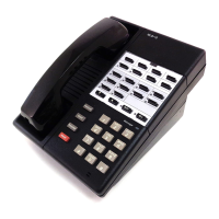
3.08 Connect the 1220A hand telephone
set
to a
telephone
base
by
plugging
an
H5AB or
H5AA (tip
party
identifying ground) cord
in
the
jacks on each component.
3.09
If
tip
party
identification
is
required,
an
H5AA
cord
must
be
u
se
d. Check
under
P-82E800 cover to see
that
screw used in tip
party
identification
sw
itch is tightened down. The absence
of a screw or screw hole
in
the identification switch
position
indicates
that
the
connection
has
been
made
in
the network
at
the factory.
3.1 O
If
message waiting lamp
feature
is required,
an H5AD cord
must
be used (Fig.
8)
. The
lamp equipped end
of
the cord plugs into the hand
telephone set.
~
When
using
these
push-in-lock
type
~
plugs
make
sure
the
contacts
are
in
proper
position
to
make
electrical
connection
with
the
mating
contacts,
and
that
the
plug
is
placed
in
the
proper
receptacle.
Either
error
will
cause
circuitry
problems
and
extreme
difficulty
in
removing
the
plug.
ISS
1,
SECTION
502-304-101
..........._H5AD
HANDSET
CORD
Fig.
8-HSAD
Handset
Cord
(Message
Waiting
Lamp)
3.11 Where a single dial light
is
involved, use a
2012A
transfor
mer
. Select a 105-120 volt
ac rece
pt
acle
not
controlled
by
a switch.
If
the
transformer
does not have
the
folded-blade prongs
use a
2A
clamp to secure
transformer
to the outlet.
Where two
or
more dial
light
sets
are
in
sta
lled,
refer
to the section on station transformers
for
use
with multiple installations.
The
illuminatio
n
of
the
dial
diminishes
with
increased
cord
lengths.
In
insta
llations
where
the
illumination
is
considered
inadequate
,
the
53B
lamp
may
be
replaced
by
a 53A,
if
the
lamp
power
is
supplied
by
a 2012A
transformer
and
the
combined
lengths
of
mounting
and
handset
cords
exceed
15
feet.
Refer
to
Part
5,
Maintenance,
for
dial
lamp
replacement.
3.12 For proper illumination
of
the dial the length
of wire between the transformer and telephone
set
should not exceed
250
feet
of
inside wire.
3.13
When
the
hand
telep
hon
e
set
is
used
in
conjunction with a k
ey
telephone
system
,
the dial lamp can be
powered
from
the
10
volt
tap
of
a
lOlG
or
equiva
lent
power supply
of
the
key
system
.
If
a 10
volt
power
supply
is
used
replace
51B
or
53
lamps with 51A or 53A lamps.
3.14 Ringing and/
or
identification ground, where
required,
is common
to
the
lamp
circuit.
Page
S
TCI Library: www.telephonecollectors.info
 Loading...