Do you have a question about the AT&T Plant Series and is the answer not in the manual?
Outlines the section's purpose: identification, installation, maintenance, and connection for the 1220A handset and bases.
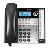
Identifies the 1220A handset as part of the TRIMLINE set, noting its relation to base components.
Differentiates AC1 bases for wall mounting from AD1 bases for desk-type installations.
Details the components required for a complete telephone set, all ordered separately.
Lists optional components like handset cords and polarity guard for separate ordering.
Mentions the 2012A transformer as associated equipment.
Lists common replaceable parts such as covers, retainers, and lamps.
Notes that the GN-2433 booklet is shipped with the set for customer use.
Highlights features of the 1220A handset, including its dial illumination and recall switch.
Lists design features of the AC1 and AD1 bases, such as factory-wiring and adjustable ringer volume.
Illustrates the interior of the AD1 telephone base, showing components and cord jacks.
Depicts the H4DB handset cord and its plug types for connection.
Describes base features like handset hanging and ringer options.
Lists key considerations for planning telephone set installation, including safety and location.
Details the procedure for removing the base housing using captive screws and a releaser.
Explains how to mount the AC1 base directly or using adapters and backboards.
Guides on terminating exposed AC1 inside wire at a common bridging point.
Addresses the necessity of exposed wire runs between the transformer and base.
Provides guidance on installing a Polarity Guard for specific signaling requirements.
Describes the steps to replace the AC1 base housing and secure its screws.
Details inserting and securing the mounting cord plug into the base assembly.
Explains connecting the handset cord between the handset and telephone base.
Specifies the H5AA cord for tip identification and checks related to its switch.
Details using the H5AD cord for enabling the message waiting lamp feature.
Guides on using the 2012A transformer for dial lights and selecting appropriate receptacles.
Discusses factors affecting dial lamp brightness and potential lamp upgrades.
Specifies the maximum wire length for proper dial light illumination.
Explains powering dial lamps from key system power supplies.
Notes the commonality of ringing/identification ground with the lamp circuit.
Warns about potential transformer damage due to ground potential differences.
Details the installation of a 426N diode for 4-party full selective or 8-party semiselective ringing.
Suggests alternatives like cold-cathode tubes or ringer isolators for high noise conditions.
Outlines wiring for portable AD1 installations using 550A jacks and 505A plugs.
Covers transformer connection for multiple portable sets with dial lights.
Emphasizes correct jack and plug installation for ground identification.
Advises briefing the customer on the telephone set's operating features.
Explains the function and use of the recall switch as an alternative to the line switch plunger.
Warns against incorrect recall switch use during calls to prevent service disruption.
Details demonstrating the three-step ringer volume control and its cutoff feature.
Defines the scope of maintenance for AC1 and AD1 bases, including ringer bias and contacts.
Refers to Division 501 for adjustments and ringer cutoff feature of the P1A ringer.
Addresses the need to replace sets with RF suppression modifications if required.
Lists field maintenance tasks for the 1220A handset, including lamp, retainer, and cord replacement.
Details replacing the dial lamp in TRIMLINE handsets using specific tools and noting lamp types.
Recommends using 53B type lamps for maintenance due to compatibility with handset versions.
Explains how to replace handset or mounting cords using a releaser tool.
Advises replacing the handset if transmission issues or an inoperative dial are encountered.
Outlines the steps for testing the hand telephone set, including dial tone and button functionality.
Continues handset testing procedures, including using a test set and component replacement if needed.
Illustrates replacing dial lamps in early production handsets with a 553A tool.
Shows the method for removing a cord from a TRIMLINE handset using a KS 16750 tool.
Demonstrates removing the mounting cord from an AD1 telephone base.
Provides the wiring diagram for the 1220A Handset and AC1 Telephone Base.
Explains notes, sequences, and color codes associated with the wiring diagram.
Presents the wiring diagram for the 1220A Handset and AD1 Telephone Base.
Clarifies notes for the AD1 base diagram, including cord length and message waiting features.
Shows AC1/AD1 base connections for 1A1, 1A2, and 6A Key Telephone Systems.
Lists notes regarding wire routing and cord handling for key system connections.
Details conversion for 1A1, 1A2, 6A KTS, showing terminal board connections.
Provides AC1 wall base connections for 2-party service, including ringer and ground notes.
Outlines AD1 desk base connections for 2-party service, with ringer and ground notes.
Specifies connections for 4-party full selective or 8-party semiselective ringing using a 426N diode.
Details P-90D231 Polarity Guard Assembly connections for AC1 or AD1 bases.
Shows message waiting lamp cord connections for 1220A handset to AC1 base.
Lists message waiting lamp cord connections for 1220A handset to AD1 base.