36
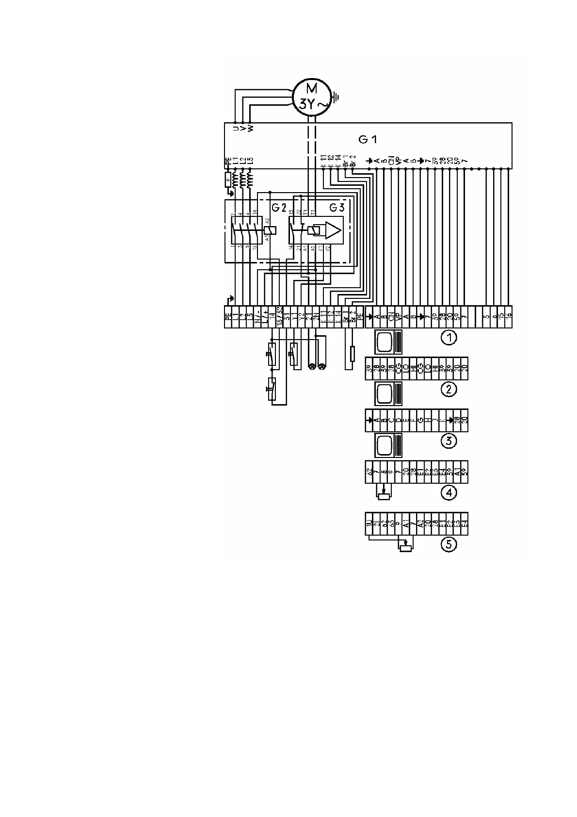
G1: Frequency converter
R: approx. 0 Ω for the TN
and TT network versions
R = 10M Ω for IT-network
version
G2: Relay
G3: PTC tripping device
L1, L2, L3: Power supply
input: power and control
N/-, L/+: control voltage
220 - 240V~ or 24V=, fuse
maximum 16A
14, 13/32, 31: I/O keys
Y1, Y2: PTC tripping
device reset
21, 2N: "Failure" message
14, 2N: "On" message
K11, K12, K14: Converter
relay outputs
Br 1, Br 2: Brake rheostat
5, 6, 15, 16: Keypad
connection (parameter
setting)
c PROFIBUS-DP at
choice
d Systembus (CAN) at
choice
e Interbus at choice
f Standard I/O at choice
g Applications I/O at
choice
Figure 13:
Overview circuit diagram of the compact drive with
relay, PTC tripping device and separate power
supply of the control voltage for all of the network
versions. For details, see the converter installation
instructions and the circuit diagram for functional unit
1-5