40
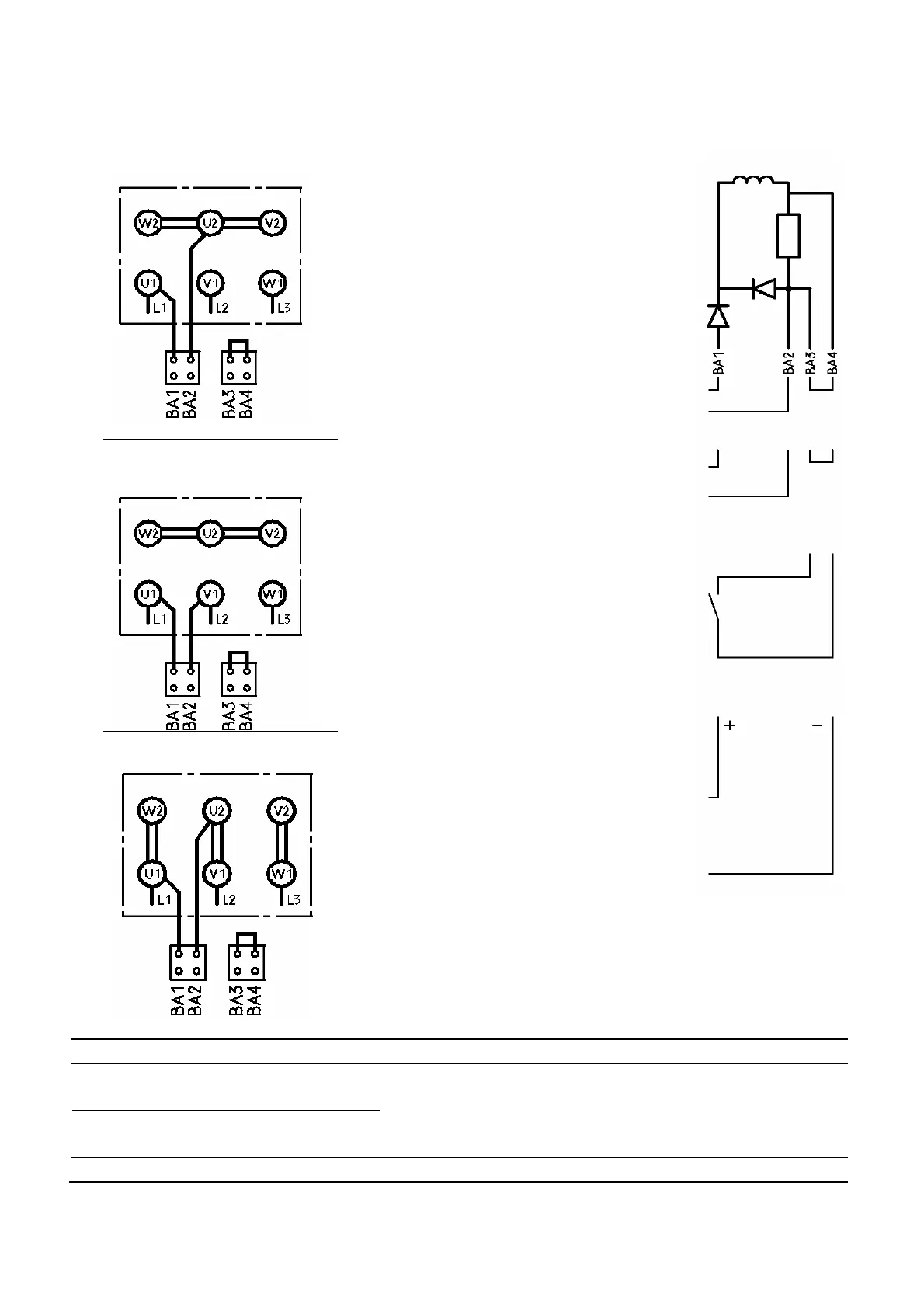
Brakemotors with incorporated brake
Brake connection via motor winding
Y circuit
Terminals BA1-BA2 can be connected
directly to the motor terminals to supply
the brake. Compare the motor/brake
voltages to determine whether the
connection is to be made on U1-U2 or
U1-V1.
Terminals BA3-BA4 must be bridged.
Y circuit
Brake
n external power supply can be applied
on terminals BA1-BA2. Check the
voltage data on the rating plate.
Terminals BA3-BA4 must be bridged.
For a rapid engagement of the brake
(DC-voltage side tripping) bridge BA3-
BA4 can be replaced by a contact. The
contact must be tripped simultaneously
with the brake power supply.
∆ circuit
In order to provide for the emergency
venting of the brake, e.g. to turn the
motor manually, you can apply a DC
voltage source to terminal BA1 + BA4
(remove any other wiring before hand
and observe the polarity).
U voltage = = U~ x 0.45
U voltage~see brake voltage on the
rating plate.
BA1-BA4
Brake
1TP1-
1TP2
Pre-alarm PTC
2TP1-
2TP2
Tripping PTC
U>2.5V not allowed Use tripping device with
PTB number or
marking II(2)G
HE1-HE2
Space heater