GasSens Gas Detection System Section 1 - Overview
O & M Manual
A14-RK, 8/06 1 - 15
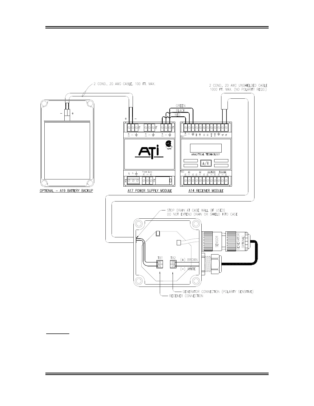
Sensor/transmitters contain two 2-position terminal blocks, one for receiver connection and one
for connection of the Auto-Test generator. Connection of the two wires from the receiver are not
polarity sensitive. These wires can be hooked up without regard to terminal position.
Connection of the generator is polarity sensitive. The generator will not function unless
connected properly. Sensor/transmitters supplied with the generator from the factory will be
factory wired. Adding a generator to an existing unit requires the installer to be sure that
generator wiring follows the diagram in Figure 1-8 below.
Analytical Technology, Inc.
Figure 1-9: Typical System Wiring, Nema-4 Transmitter Version (ATI-034)
CAUTION: Be very careful when removing the knockouts on the sensor/transmitter
enclosure. A small bladed screwdriver tapped firmly in the knockout recess is
all that is necessary. Do not drive the screwdriver blade into the transmitter
enclosure or it may strike the circuit board and cause component damage.